Recently, our company was hired to remodel a 1950s beach cottage just south of San Francisco. The job included repairing the house’s seriously damaged foundation.
Our original plan was to shore up the building, replace the support beams, and reuse the existing wood piles. But once we got the house supported by cribbing and temporary steel beams and started excavating around the piles, we found that they extended only 4 or 5 feet below grade rather than the 15 to 20 feet we’d been expecting.
Since the existing foundation could not be saved, we had to design, gain approval for, and build a new one from scratch. And, with the house up on cribbing, we had to hurry. The house mover’s liability insurance would not cover us if the shoring remained in place for more than 90 days, a real concern with the winter storm season approaching. If a big wave hit before the foundation was done, the cottage could be destroyed.
Although we had already planned to drill new piers for the decks, these weren’t an option for the house unless we moved it out of the way or drilled from below with a handheld rig. But moving the house would be too expensive, and drilling with a handheld rig would be difficult with so little headroom above and so many stone cobbles in the sand and gravel soil below.
Instead, we decided to remove the piles and support the cottage with concrete columns extending up from a modified version of a mat foundation, which was designed for us by Joshua B. Kardon, a structural engineer in Berkeley, Calif. A mat foundation is a thick and heavily reinforced concrete “slab” stiff enough to span weak areas of soil. The mat is usually continuous, but this one would be grid-shaped, because we planned to leave the house where it was and form around the temporary cribbing. We would place the foundation in a monolithic pour, so that the cured grid and columns would act as a unified whole.
Replace the Beams First
The design called for new Port Orford cedar glulam support beams, which we decided to install before forming the mat and columns. That way, there would be fewer things in the way. We could hang the beams from the joists, install the column caps, and then form and pour up to the caps (Figure 3). Since the house was so close to the ocean, we opted to use only stainless steel fasteners and hardware for extra resistance to corrosion.
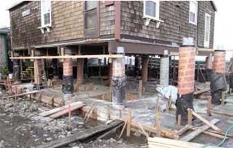
Forming the Grid And Columns
On the plans, the foundation looked like a perforated mat — a grid of intersecting wide grade beams, four going one way and four others crossing at 90 degrees. Each grade beam measured 4 feet wide and 18 inches thick. Of the 20 columns extending out of the grid, 16 would support the cottage and four would support the deck (see “Mat Foundation Details”).
Steel reinforcing. The grid was heavily reinforced, with each grade beam containing 10 #6 bars, five on top and five on the bottom. The crew connected them with #3 ties every 14 inches on-center and spaced them off the ground with small precast blocks called dobies.
The columns projecting up from the footings contained cages of four #7 bars with #3 ties 6 inches on-center. We had the cages tied off site and sent out to be hot-dip galvanized. Before tying the cages into the grid, the crew slipped 16-inch-diameter Sonotubes over them. Fourteen-inch columns would have been strong enough, but with all that salt water around, we upsized them to get an extra inch of coverage over the steel.
Special concrete for a saltwater environment. Standard concrete is porous and prone to cracking, because as the material hydrates, bleed water forms internally around the aggregate. Once the concrete dries, there are open pores where the water used to be. On larger pours, the heat of hydration can cause thermal shrinkage cracking all by itself. We were concerned that salt spray — which attacks and corrodes even galvanized steel ferociously — would make its way to the rebar through the cracks and pores that would inevitably exist if we poured the foundation with standard concrete. We wanted the concrete on this job to be impermeable and to contain no cracks at all.
With advice from the manager of our local concrete plant, we came up with a mix containing water, cement, fly ash, 1/2-inch and 1-inch aggregate, two types of sand, fiber, and three additives. Along with the varied size of the sand, the large and varied size of the aggregate would limit shrinkage — but it also would make the material difficult to pump. Still, because access was poor and we wanted to do a monolithic pour with close to 80 yards of concrete, we needed to pump.
While a concrete pumper’s natural response to these circumstances might have been to add more water, we wanted to avoid weakening the concrete, which is why we dealt with the problem by using additives that made the mix easier to pump.


