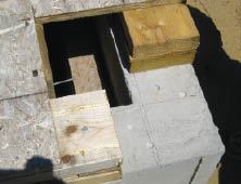
The moment frame begins at the foundation. MDO templates ensure …
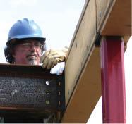
I’m an independent framing carpenter and experienced ironworker. Over the years, that combination of skills has landed me a number of unconventional and challenging projects. The contemporary home I’ll discuss in this article featured large expanses of glass separated by slender columns supporting a flat roof. Because I work in a 110-mph coastal wind zone, wall bracing was an especially vital consideration.
But in a facade composed of more glass than studs and plywood, there’s little opportunity to incorporate conventional shear walls or engineered panel systems. Instead, you have to resort to a steel moment frame. Whether bolted or welded, the moment connections in a steel frame don’t allow the joint rotation seen in wood-to-wood connections and can therefore resist wind and structural loads that would overwhelm common wood connections.
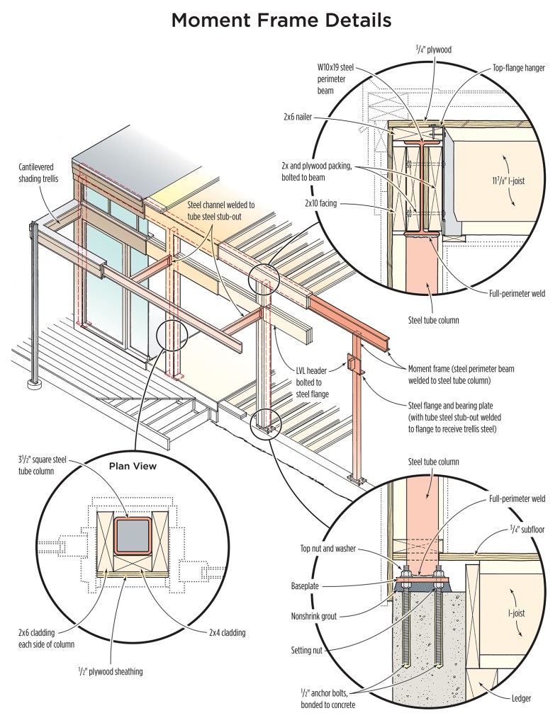
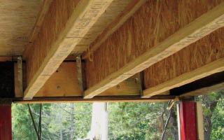
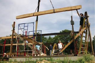
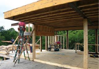
For this house, the architect and the engineer designed a moment frame — 11-foot-tall steel columns topped by steel I-beams — that wrapped the building’s perimeter. Wood I-joist roof framing hung between the interior faces of the perimeter beams. It was my job to integrate all this steel within the 2×6 walls of a conventional wood frame.
Layout
The engineer specified 3 1/2-inch-square tubing columns supporting 10-inch-tall, wide-flange (W10x19) steel perimeter beams. To provide nailing for plywood sheathing and finish trim, I decided to box the columns on three sides with 2-by lumber, a 2×4 on the exterior face and a 2×6 on either side to match the general exterior wall framing. As a result, the steel framing line lay 1 1/2 inches inside the actual building line — which was helpful because part of the home was built on an existing and somewhat irregular foundation, and this allowed some fudge room for squaring up the new layout.

Tim Healey
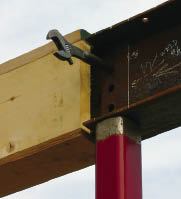
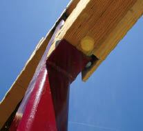
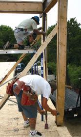
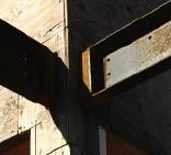
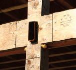
Where glass walls eliminate the possibility of shear panel construction, welded connections between steel columns and beams provide the necessary resistance to lateral wind pressure. To simplify the application of wood finishes, the moment frame is clad in nonstructural framing lumber attached with powder-actuated fasteners.
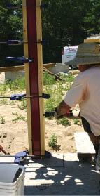
Following the plans, I first transferred the centerline spacing of the 29 columns to the existing deck, then snapped lines representing the inside face of the 2×6 perimeter walls, as well as perpendicular lines for key partitions and roof beams. I like to use black chalk because it’s highly visible and remains so for months under tough job-site conditions. I wanted these lines to be visible later when it was time to true the perimeter beams to a laser plumb line.
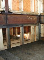
Accommodating elevation changes. The columns weren’t fastened to the wood framing, but directly to the concrete. So at each column location, we cut away the floor framing and mudsill, exposing the foundation. Next, I took accurate elevation readings with a rotating laser and found a difference of 1 1/2 inches between high and low points in the floor joists. Because the lot slopes, the foundation was also 8 inches higher at the back of the building than in front.
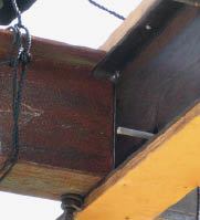
I picked a value about midway between gross high and low as my baseline against which to establish the top-of-steel (TOS) line. The architect specified a finished ceiling height of 10 feet above the finished floor. To determine the top of the roof framing, I added ceiling plaster and I-joist dimensions, then deducted the thickness of the 2×6 nailer affixed to the top of the perimeter beam. This nailer established the top of the I-joist framing and enabled the deck plywood to finish to the outer edge of the steel.
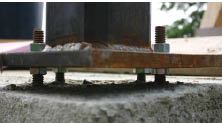
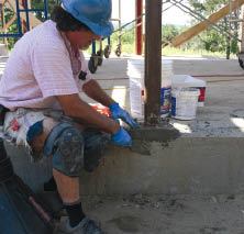
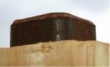
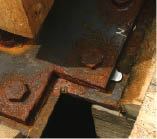
Due to the unevenness of the original foundation, I specified four averaged baseplate elevations and column lengths for the 29 columns. Four 1/2-inch-diameter anchor bolts bonded into the concrete held the baseplates. To accommodate irregularities in the surface, it’s standard practice in steel construction to keep column baseplates about one inch above the concrete. When the column is first set, it rests on setting nuts threaded onto the anchor bolts. Turning these nuts one way or the other adjusts the column both to plumb and to its final height. Once set, a second set of nuts and washers secures the column to the anchor bolts, and later the void under the plate is filled with nonshrink grout.
Shop Fabrication
My brother, Matt, owns Wellfleet Steel Works, which specializes in fabricating and placing structural components and often provides the steel for my jobs. When working with steel, we try to keep to a minimum the variations among parts of each type. For example, we make a standard baseplate for all corner columns, and we keep the centerline spacing on bolt holes the same for every beam connection. It’s common sense: Repeatable details lead to fewer mistakes.
I make anchor-bolt patterns for the baseplates out of scrap MDO plywood or PVC trim board. We make sure our patterns — unlike the CDX patterns Matt often receives — are dead accurate. I make them in triplicate, using three layers of material screwed together and milled at once to ensure a precise match. I drill the bolt-hole centers on a drill press, using a 1/4-inch bit. One pattern goes to the person making the columns, and the other two go back to the job site to guide anchor-bolt installation.
Variations in steel members. It’s commonly assumed that steel members are uniformly straight and dimensionally true, with no twisting or bowing, but this isn’t the case. Though steel is better than lumber, irregularities exist. You have to sight each piece to orient it properly in the frame. Severe bowing is impossible to correct and must be rejected. Flange widths can vary, even on the same beam. Fortunately, on this job, every piece was straight.
Bolt or Weld?
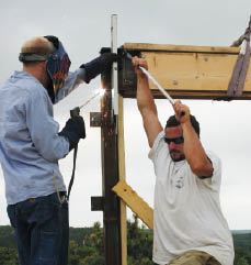
The moment connections we make are of two types, bolted and welded. I prefer welded connections because they’re stronger and easier to fit — you can make adjustments with a grinder or a torch right up to the last minute. The fitting of a welded joint should be precise, with parts fully touching, though the weld can bridge gaps up to 1/8 inch.
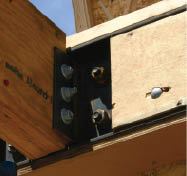
Bolted connections, on the other hand, require precise layout of holes, usually six to eight per connection — a time-consuming process. Also, we drill holes only 1/16 inch larger than the bolt size, so just one misaligned hole can prevent installation of one or more bolts, or limit fine adjustments between the parts. Then you have to “egg out” the errant hole to accommodate the binding bolt.
Nevertheless, engineers generally prefer bolted connections because the special-order bolts carry an ASTM rating, giving them known performance properties. Welders like bolted connections, too, because bolting cuts down the amount of welding that has to be done on site — often from a ladder. And because they go together more quickly, bolted connections also reduce the crane time.
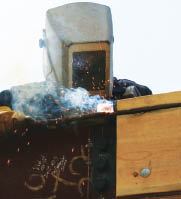
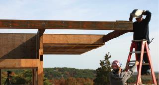
On this job, half of the right-angle connections between beams called for bolted angle clips. The rest were specified as full perimeter welds, meaning a full-contact, coped fit between the beams and a continuous weld around the entire joint — a task that can take 20 minutes or longer.
The columns were also welded directly to the beam bottom flanges; we made simple square cuts at the tops, then beveled them for welding to the beam flange.


