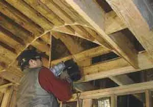
The company I work for builds spec homes. One of the ways we dress them up is by adding barrel-vault ceilings. Except for the layout, these impressive architectural details are not that hard to frame. A carpenter and helper can do it in four to five hours.
Our vaults are typically installed in a rectangular opening in a hallway or master bathroom. As a result, the opening is rarely more than 6 feet wide or 12 feet long. Framing a larger vault wouldn’t be any different, but we’ve never had the space.
Geometry of a Barrel Vault
The surface of the barrel is part of the inside surface of a cylinder; a section through it is an arc of a larger circle. The ends of the vault can be plumb and flat, or curved like the barrel itself. We usually make them curved.
Like a hip roof. The layout for this kind of barrel is similar to that of a regular hip roof — one where all the pitches are equal. On a hip roof, common rafters run up from the sides and meet at the ridge. On a barrel vault, half-arc segments run up from the sides and meet at the high point of the vault. If the vault is small enough, you can make the entire segment from a single piece of plywood.
A hip roof has a single common rafter, called the king common, at each end. The king common runs from the top plate to the ridge board. The same is true of a barrel vault except that the end piece is half of an arc segment, and instead of hitting a ridge it meets the midpoint of the last full arc segment in the barrel.
The hip is an ellipse. The vault framing also includes hiplike pieces that come in from the corners at 45-degree angles. In plan, they look exactly like hips, but from the side you can see they’re curved. Because they’re formed by the 90-degree intersection of two cylindrical curves, their shape is actually an ellipse.
Ceiling Opening
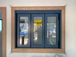
The first step in framing a barrel is to create an opening for the vault to go into. If it’s on the top floor, we’ll cut out some ceiling joists and head off the opening. That may not be possible on a lower floor, in which case we’ll drop the surrounding ceiling by framing in a soffit. The size of the opening might be specified by the designer; if not, we’ll come up with a size that seems proportionate to the room. In the project photographed for this article, we framed the opening about 12 inches off the main walls of the room.
After the opening is framed, we double-check to make sure it’s square and the sides are reasonably parallel. Then we measure the distance across the opening at several points and use the average distance to determine the curves for the barrel.
Determining the Radius
Once we know the size of the opening, we decide how tall the vault should be at its highest point, then calculate the radius required to hit both edges of the opening while passing through the high point. To put it mathematically, we know a chord length (the width of the opening) of a given circle, we know the plumb distance from the center of the chord to the circumference of the circle (the height of the barrel), and we need to find the radius of the circle.
The easiest way to get the answer is to use a construction calculator that has a trig function. I use the Construction Master Pro Trig Plus III. For the vault shown in this article, which is 48 1/2 inches wide and 12 inches high, I punch in the following sequence:
48 1/2-INCH RUN
12-INCH RISE
CONV DIAG
The screen displays the radius of the arc, in this case 30 1/2 inches. You can also use algebra to calculate the radius.
Making Arc Segments
We make the arc segments out of plywood. You could use OSB, but that would make it harder to see the layout and make clean cuts. Whenever possible, we try to gang-cut the pieces with a jigsaw. We then cut one in half to make the king commons for the ends.
Laying Out the “Hips”
The first time we framed this kind of vault, we didn’t fully understand how to lay out the ellipses. When our initial efforts failed, we installed the segmental arches, or “commons,” then scribed the ellipses by taping a pencil onto a 4-foot level and sliding the level along the plane of the barrel to mark the shape onto an oversized piece of plywood that had been inserted where the “hip” was to go. The method worked, but it was time-consuming and the curves weren’t as fair as they should have been.
The next time around, I called Joe Fusco, a cabinetmaker I know in New York, to ask what we were doing wrong. He sent me a drawing that explained how to lay out the ellipses; without it I’d probably still be tracing the curves.
There are two numbers you need to know to lay out an ellipse: the length of the major axis and the length of the minor axis. If you have these numbers, you can also locate the two focus points. Once you have those points, all it takes is some picture-hanger wire and a pencil to draw the curve.
In a vault of this type, the minor axis matches the diameter of the cylinders from which the barrel is formed. Since we needed to draw only the top half of the ellipse, we used half the diameter, the radius of the circle — 30 1/2 inches.