I run a specialty millwork shop in Narragansett, R.I. Over the last 25 years, I’ve developed a strong working relationship with my oldest and largest customer, Baud Builders. One of the first things Dave Baud and I do when we review a set of plans for a new home is identify out-of-the-ordinary architectural components that can be built off-site in my shop. This approach takes some time-consuming tasks off the framing crew’s back, allowing them to focus on getting the basic building shell closed in.
That’s how we handled the front entry featured here — an arched-roof portico projecting between gambrel gables above a rounded deck. The front corners of the roof rest on composite columns standing on flared-skirt half walls. The gambrel eaves terminate on the portico roof, creating as complicated a junction of rooflines as you’re likely to encounter.
When I began the job, only the height and depth of the entry inset had been established on site, but the window immediately above the portico roof had not yet been framed. So to play it safe, everywhere that the porch assembly would join the main structure, I allowed 1 1/2 inches of clearance for fitting and shimming. We also had the site crew hold the adjacent roof framing back a couple of feet until the portico roof could be dropped into place.
Keeping It Light
I began by making the architrave, the perimeter beam that supports the roof. Instead of using framing lumber, I built a box beam with 1-by pine and MDO plywood. Hollow construction allows a higher degree of accuracy and dimensional control than conventional framing. And hollow members are strong but light, so they’re easier to move around in the shop and onto the site for final assembly. Also, the open construction provides drying airflow within the structure and enables the electrician to install downlights and run wires without drilling. The architrave beam became the platform on which I built the roof.
Roof trusses. For the barrel-roof framing, I made lightweight open trusses with curved 2×4 chords sandwiched between 3/8-inch AC plywood skins. The front part of the roof spanned 16 feet, so I was able to use two lengths of 8-foot plywood laid out in mirror image to make the skins. We joined the skins end-to-end with plywood mending plates and fast-setting, permanent HiPur hot-melt adhesive (800/669-4583, titebond.com). To make the chords, we kerfed the 2x4s on a chop-box at 3-inch intervals, then bent them against stops hot-melt-glued to the workbench.
I made the roof in two sections, front and rear, to make it easier to scribe to the building if needed. The rear section was sized to fit within the entry recess, a span of about 9 feet. These skins are single sheets extended at either end with plywood fillers.
We sheathed the trusses with three layers of 3/8-inch AC plywood, fully bonded with spreadable Excel polyurethane adhesive (800/779-3935, excelglue.com) and stapled. We stepped the plywood layers back from the joining edges so that we could make a seamless union on site.
Half Walls
Next, we tackled the two L-shaped half walls. To ensure square corners and bottom-up uniformity, I cut six identical plate patterns out of 3/8-inch plywood and laminated each of them to pieces of 2×8 plate stock, then trimmed the plates to uniform size with a pattern bit. Four of the plates were used in the half walls, and the other two were set aside for mounting on the deck framing as installation base plates. We framed the walls with pressure-treated lumber and sheathed them with 3/8-inch AC plywood. We extended the sheathing 1 1/2 inches beyond the bottom plate to create a nailing flange, keying the wall to the base plates on the deck framing.
Construction Details
For the flared wall profile, we cut curved blocking on a band saw, using a pattern jig to speed the operation. The same flare wraps the entire building, so we provided nearly 1,000 of these blocks in all. They’re set on a pressure-treated cleat and nailed to the wall at regular intervals. We glued and stapled 3/8-inch sheathing over the blocks, followed by a wider sheet of 1/4-inch lauan plywood to help fair the curve onto the wall.
The railing cap is 8/4 mahogany, mitered like an upside- down “V” to shed water and glued with two-part West System epoxy (866/937-8797, westsystem.com), a gap-filling and completely waterproof adhesive. We avoided fillers or plugs by simply gluing the cap to the wall with polyurethane construction adhesive.
To capture the composite structural columns supporting the roof, I made circular top and base plates out of cedar. I’ve found that a surprising amount of moisture can condense inside these columns, so I drilled weep holes around the base plates. The plates are glued with epoxy and screwed to the railing caps. I scribe-fit the base of the proprietary decorative plinths to the peaked railing profile and added weeps along their front and back edges.
Framing the Deck
The pressure-treated deck framing is an integral part of the portico and was built in the shop along with the other components. I made the main body of the deck as a unit and its bowed front as a bolt-on section. I drew the radius on the shop floor with a trammel and built directly to it. To make the bowed rim joist, we kerfed a 2×10 at 3-inch intervals to within 1/4 inch of the face. To form the concentric starter tread, I made uniform lookout blocks and hung them by cleats from the back of the deck’s rim joist at even intervals. The resulting radial layout created a built-in bending form for the starting riser.
Laminated Decking and Trim
We used 5/4 red meranti for the decking. To make the curved tread and deck nosing, I ripped 1/4-inch strips from the meranti and used the deck frame as a bending form. If you keep track of the rip sequence, you can reassemble the boards with the grain pattern more or less intact. We brushed the bonding faces with two-part epoxy, wrapped the strips in 4-mil poly, and used plenty of clamps. To minimize cleanup, we protected the outside edges with a bond-release tape. After the epoxy set, we trued the surfaces by sending them through a planer. The finished thickness wound up at just under an inch, so I passed the rest of the decking through the planer at its final setting to match.
To complete the deck module, we cut all of the planks to fit against the curved nosing and labeled the boards in sequence for installation on site.
Roof trim. The laminating process was much the same for the roof’s arched trim, which we made from clear western red cedar.
The roof’s exposed end panel is protected with Ice & Water Shield (800/444-6459, graceathome.com) and faced with 1/2-inch-thick Azek sheeting (877/275-2935, azek.com), which we installed over a short overhanging cap that the roofing contractor clad with lead-coat copper in the shop. I cut the Azek to fit loosely and let it float behind the cedar trim. This allows the PVC material to move freely with thermal expansion. I also set the panels on skip blocks so that any water that found its way behind the panel would drain out again.
Installation
With a crane standing by, we loaded the components on a flatbed trailer and towed them to the site. We first lifted the deck frame into place, leveling and shimming it, then bolting it to the building with LedgerLok screws (800/518-3569, fastenmaster.com). The base plates for the half walls were already screwed to the deck frame in the shop. I patterned their locations directly from the architrave, ensuring accurate alignment with the column plugs overhead. All we had to do was to lift the two walls off the truck and fit them onto the base plates. We then lag-bolted the walls from underneath, through the base plates.
The composite columns went in next. We set them on the railing cap and screwed them to the blocks. The plinth bases slipped down to cover the connection.
We had added secondary fascia trim to the architrave in the shop, to cover Cor-A-Vent strips (800/837-8368, cor-a-vent.com) that provide ventilation. The ceiling was left open, to give the electrician full access for wiring and lights. We would install the beadboard later, on site.
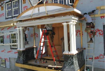
After we screwed the column tops to their corresponding cedar plugs on the architrave, we were ready to lower the roof sections into place. We installed the front section of the roof first, carefully lowering it so that the trusses dropped in between the vertical hold-downs protruding from the architrave. The rear section of the roof required some scribing before it could drop into place. We then completed the roof sheathing between the two sections by gluing and stapling stepped layers of precut sheathing at the joint.
The entire installation took less than a day, start to finish. Total shop time ran about 250 man-hours. With the portico in place, the framers completed the abutting roof lines and added crickets to either side of the angle bay. The roofing contractor finished the portico roof with lead-coat copper flashing and an EPDM membrane.
Mike Rand owns Narragansett Housewrights in Narragansett, R.I.


