Despite the rapid growth of radiant floor heating, fin-tube baseboard is still the staple of American hydronic heating. Hydronic baseboard was first introduced in the late 1940s as a lightweight and easily installed alternative to cast-iron radiators, and its current U.S. sales now exceed 11 million linear feet annually. With a proven service record of several decades, it will undoubtedly retain a large portion of both new and retrofit markets for hydronic heating.
This article discusses the procedures necessary to ensure a top-quality hydronic baseboard installation — one that puts the right amount of baseboard in the right locations, and eliminates the noise problems that can plague carelessly installed systems.
Convective vs. Radiant Heat
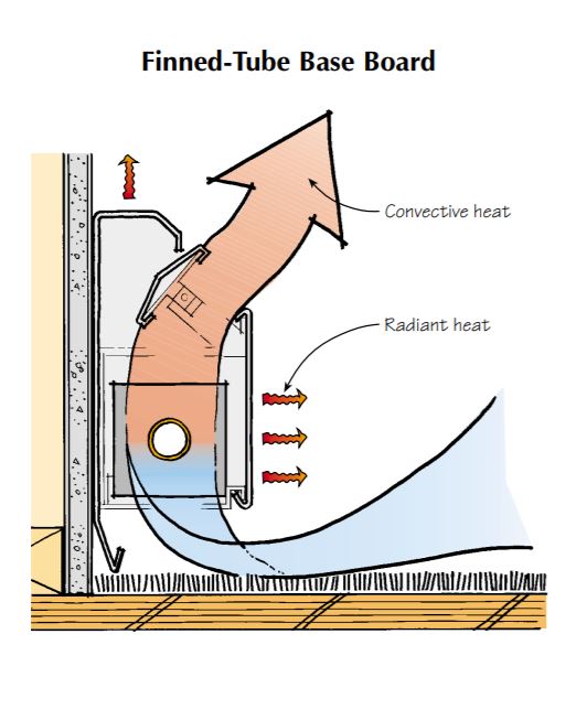
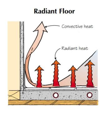
Most of the heat released from a typical radiant slab is, of course, by radiation: The hot water in the embedded tubing warms the concrete, which at its surface radiates heat to nearby people and furniture. By contrast, most of the heat produced by fin-tube baseboard is convective: Hot water passing through the element quickly heats air between the fins, setting the convection process in motion. Warm air rises through a slot at the top of the enclosure while cool air flows in at floor level to replace it.
Although produced by several manufacturers, most brands of fin-tube are similar in construction. The element consists of a 1/2- inch, 3/4-inch, or 1-inch copper tube with mechanically attached aluminum fins. It rests on support cradles within a painted steel enclosure. Most baseboard enclosures have an adjustable damper at the top that can be used to reduce heat output.
Tim Healey
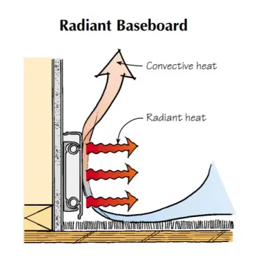
Most of the heat produced by radiant floors (as well as by cast-iron, Euro-style radiant baseboard, below) is in the form of heat waves, though some convection currents are also created.
Tim Healey
Heat output from baseboard depends largely on water temperature. The chart below shows how pronounced this effect is for a typical residential system. As water flows through a series piping circuit containing several baseboards, its temperature is constantly decreasing. To select the proper length of baseboard for a room, it’s necessary to estimate the water temperature at the location of the particular baseboard within the circuit. (For a technical explanation of how to size baseboard, see “Sizing Baseboard.”)
Baseboard heat output is tested under an impartial standard called the IBR Testing and Rating Code for Baseboard Radiation. The results appear in manufacturers literature as heat output per linear foot of finned element (which is typically 3 to 6 inches less than the length of the enclosure). Ratings are usually given for several water temperatures and two water flow rates. (For example see this chart from Slant FIn [PDF].)
A footnote to the ratings indicates that 15% has been added to the tested thermal performance values to account for something called the “heating effect factor.” The origins of this go back several decades, to when baseboard was being compared with the freestanding cast-iron radiators found in older homes. The assumption was that the baseboard would be immersed in a pool of cool air near the floor and would thus give off more heat than a standing radiator. (The greater the temperature difference between the air and the hot water, the greater the heat transfer.) The tested ratings were increased 15% to account for this.
Although this may have been an accurate assumption in 1950s housing, it’s not the norm today, because houses are tighter and more evenly heated, with fewer drafts and less air stratification. I prefer to size the baseboards based on their true tested performance. To do this when using a published chart, just divide the heat output value by 1.15. Otherwise you risk putting too little baseboard in a given space.
Zoning for Comfort
The ability to accurately control heat delivery among several independent zones is a major advantage of hydronic heating. The more zones there are, the greater the ability to adjust the system to individual preferences. Most clients instinctively like the idea of having lots of zones until they realize the extra cost involved. Sometimes, too, people will spend the money for elaborate zoning, then seldom use it. Here are some guidelines for matching zoning needs to the budget.
Zone controls are not always necessary. Remember that in many cases baseboard systems can be designed to keep different parts of a building at different temperatures without adding zone controls. Simply closing the damper on a baseboard can reduce heat output to a room by about 50%.
Zone selectively. Areas that aren’t used much are obvious candidates for zoning. Examples include workshops, guest rooms, and basements. Energy savings will easily repay the extra cost of putting such areas on a separate zone.
Bathrooms are good candidates for separate zoning. With the bath zoned separately from the bedroom, the homeowner can sleep in a cool room, then step into a toasty-warm bathroom for a morning shower.
Consider other heat sources. Heat delivery to sunny rooms and areas with fireplaces or woodstoves should be able to be interrupted without affecting other areas of the house.
Zoning Strategies
The most common way to build a zoned system is to use a separate piping circuit to and from each zoned area, equipped with either a circulator or a zone valve. Heat input is controlled by individual thermostats in each zone. Hot water flows through the zone circuit only when its thermostat is calling for heat.
Although both circulators and zone valves have been used in thousands of systems, I prefer circulators. The cost is slightly higher, but so is the long-term reliability. If you install a multi-circulator system, be absolutely sure a “flow check,” or spring-loaded check valve, is installed in each zone circuit to prevent off-cycle heat migration and reverse flow.
Monoflo piping. One piping alternative is called a “monoflo” system. With this approach, the baseboard in each room has its own thermostatic valve and can be separately controlled. The piping is arranged so that hot water is always flowing through the piping loop from which all the baseboards are “tapped.” This creates a constantly circulating loop of heated water from which any of the individual baseboards can extract heat when needed.
A thermostatic radiator valve (TRV) piped into each supply riser regulates flow through its baseboard as necessary to maintain the desired level of comfort in the room (see photo at left).
Home run piping. Another zoning technique, relatively new in the U.S. but common in Europe, is the “home run” manifold system. Each baseboard gets its own supply and return line, usually of PEX or PEX-AL-PEX tubing. All supply lines begin at a supply manifold like that used in radiant floor systems, and all return lines go back to a return manifold. Zone control is provided in one of two ways: with low-voltage valve actuators mounted on the manifold valves and wired to thermostats or with non-electric TRVs on each baseboard.
Layout at the Boiler
The arrangement of components near the boiler has undergone some changes in the last few years. The illustration below depicts a typical arrangement for a system with three heating zones and a separate zone for domestic water heating. One important change is the placement of circulators on the supply side of the boiler and downstream of the system’s expansion tank. This makes air purging simple, often eliminating the need to “bleed” air from the baseboards. The traditional air scoop used in older systems is being replaced by a newer device called an air separator, or de-aerator, which can capture even microscopic air bubbles and eject them from the system.
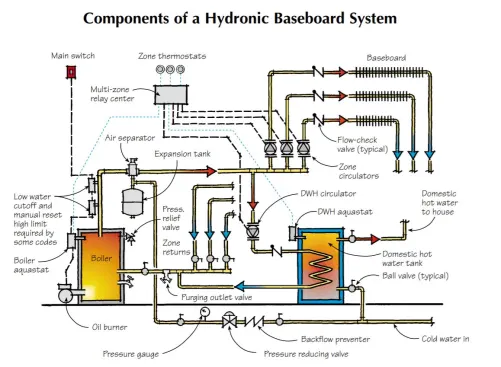
Tim Healey
In contemporary hydronic installation, the circulators are placed on the supply side of the boiler downstream from the expansion tank, making it easier to purge air from the system. The air separator is also an improvement over traditional in-line air purgers.
Notice, too, that all the wiring for the system’s circulators and thermostats has been consolidated into a single control panel called a multi-zone relay center. Several manufacturers now offer a relay center, which greatly simplifies installation and reduces cost compared with systems that use a number of single zone controls with a separate 24-volt thermostat for each zone.
Also disappearing is the traditional tankless coil for domestic water heating. Taking its place is the indirectly-fired storage water heater, of which dozens of models are now available. In this type of system, the boiler fires only when there’s a demand for space heating or water heating rather than inefficiently maintaining a minimum water temperature year-round. Most multi-zone controls have a switch that can be set to provide “priority” domestic water heating. In this mode, all space heating is temporarily suspended during DHW heating, allowing full boiler output to quickly heat the tank.
Distribution Piping Options
Although type-M copper tubing has long been the standard for hydronic distribution circuits, it now has some serious competition, in particular from crosslinked polyethylene (PEX) tubing manufactured with an oxygen-diffusion barrier (ASTM F876). A number of companies now market PEX tubing along with brass fittings for making either soldered or threaded connections. The tubing can easily be snaked through joist cavities where installing rigid piping is all but impossible — a tremendous advantage in retrofit jobs. A variation is PEX-AL-PEX composite tubing, which has an inner and outer layer of PEX bonded to a welded aluminum core. PEX-AL-PEX manufactured to the ASTM F1281 standard is rated for service conditions up to 210°F at 115 psi. After being uncoiled, PEX-AL-PEX tends to retain its shape better than standard PEX. Its thermal expansion is only about one-seventh that of PEX, because it’s controlled by the aluminum core rather than the plastic.
Installing Baseboard
Although it’s possible to install baseboard almost anywhere wall space is available, placement can affect room comfort. The preferred location is always along exterior walls, specifically under windows. The rising current of warm air from the baseboard counteracts the draft effect of the cool window and wall surfaces, and also helps prevent interior condensation on the glass during very cold weather. A careful baseboard layout should also consider furniture arrangements, door swings, and obstacles such as wall columns (Figure 5).
Whenever possible, talk over baseboard placement with the homeowner before doing a final layout, remembering that compromises are inevitable. Here are some other points to consider.
Avoid moist locations. Baseboard is not well-suited to the moisture levels of heavily used bathrooms, especially when placed next to or behind a toilet. The enclosures will start to rust within a couple of years. Since available wall space in most bathrooms is minimal, a panel radiator is often a better choice, though it will cost two to three times more for the same heat output. Another option would be to use underfloor heating, which is also more expensive.
Leave an air space. When baseboard is installed before finish flooring, remember to leave at least a 1-inch space beneath the enclosure. This ensures that the finish floor will not block air coming into the enclosure.
Locate floor framing. Before mounting the baseboard enclosure to the wall, be sure to locate the floor framing so you don’t have to butcher a joist to make room for the riser pipe from below. Try to keep riser pipes at least 2 inches away from any framing to make soldering easier. In most cases you can get a measurement for the riser pipe holes by sliding an elbow onto each end of the element and measuring between the centers of the elbow sockets. If the design requires a flow balancing valve or thermostatic radiator valve on one end of the element, dry-assemble the components before measuring.
Drill oversized holes. After marking this center-to-center distance on the floor, use a bit that’s at least 3/8 inch larger than the outside diameter of the riser piping to drill the holes. This provides space for the element to expand without jamming the riser against the side of the hole. For single-piece elements, you can solder the element and any fittings and valves together, then lower the whole assembly into the enclosure. Be sure to support all fittings so the assembly is not twisted when soldered. When set into the enclosure, be sure the element rests on the support cradles provided. Some manufacturers supply plastic expansion cradles that prevent metal-to-metal contact, and minimize expansion noise. For situations where a baseboard must be supplied and returned from the same end, install a vented 180-degree “return” fitting at the far end, and route the return pipe back through the enclosure above the element.
Preventing Noise
Preventing noise from thermal expansion is an important part of piping installation. Where copper tubing is suspended beneath floor joists, use the plastic-coated wire hangers with pointed ends that drive into the joists. These hangers flex as the pipe expands, preventing the noise you would get if the pipe were expanding inside a rigid support.
With I-joists, use a filler block in the web space before using this type of hanger. Don’t drive the points into the I-joist flanges, or you’ll damage this key structural component.
Support 1/2-inch and 3/4-inch tubing at intervals not exceeding 4 feet. Supports for 1-inch and 11/4-inch tubing should be not more than 6 feet apart. PEX tubing should be supported about every 30 inches.
Make sure all holes in the joists are aligned. Again, drill holes at least 3/8 inch larger than the outside diameter of the piping. Never rigidly fasten the copper tubing to any framing, and don’t wedge a length of pipe tightly between any rigid surfaces. Be sure hangers are rated to operate at temperatures at least 20°F above the design water temperature of the system — typically 180°F in residential systems.
Pressure Testing
When the piping system is completed, it’s time to test for leaks. This is best done with compressed air rather than water (unless you like running through buildings desperately searching for shutoff valves). Don’t get smug and “blow off” this step. I know guys who could probably solder pipe in their sleep, but still religiously test every system before the piping gets covered up.
Before you pressure test, make sure all air vents are tightly sealed, and all inline valves are open. Add air to the system with a Schrader valve (like the valve on a tire). Pump the system up to 20 to 25 psi — any higher and air starts leaking from the 30 psi relieve valve. If all’s well, the pressure should remain stable for at least 12 hours. If the pressure slowly decreases over a few hours, check all joints by brushing on a solution of dish detergent or a commercially available leak detection fluid, and look for bubbles. Threaded joints tend to be more prone to leaks. Track down any leak and fix it before covering the piping or adding water.
Charging the System
If pressurized domestic water is available on site, the system can be filled by closing the isolation flanges on all but one of the zone circulators, opening the purging outlet valve, and lifting the fast-fill lever on the pressure reducing valve. Water flows into the boiler and up through the system piping. As the boiler fills, air exits through the air separator. The water continues up through the open zone circuit, pushing most of the entrapped air ahead of it. Eventually the water-air mixture makes it back to the open outlet valve. After a minute or so the exiting stream will be relatively free of air bubbles.
Open the next zone circuit and close the first. Repeat the procedure, one zone circuit at a time, until all the zones are purged. Reset the fast-fill lever and close the purging outlet valve. Most of the air, other than that dissolved in system water, has now been expelled from the system. The air separator will get the rest during the first few days of operation.
When a system like the one in Figure 4 is first turned on, what happens depends on the control settings. If they’re set for DHW priority, the DHW zone will be the only one operating. Assuming the DHW tank has water in it, set the tank thermostat to 100°F and wait a few minutes for this load to be satisfied.
To check space heating, turn each zone thermostat all the way up, one at a time. The boiler should fire up as each zone is turned on. Don’t be surprised if you still hear slight gurgling sounds in the piping. Expect to hear occasional air hissing from the air separator as the water gets hotter. Make sure the boiler stops firing when it gets up to the aquastat setting (170°F to 180°F for a typical baseboard system).
Be sure to check out the rest of the Radiant Heating Skills Workbook.