A quick review of the prints told me that this renovation was going to be different. There would be the usual Hoboken, N.J., hurdles, of course — limited parking, virtually no backyard access, and inconvenient curbside deliveries — which would make delivery of materials for the home’s new garden-level media room a logistical obstacle course. But the project also involved a unique challenge that would make things even more interesting: We would be cutting an opening large enough to accommodate a new 12-foot-wide, four-panel glass door in a 12-inch-thick, 30-foot-high brick wall. To install a steel header for the door, we’d first need to shore up 22 feet of brick masonry above the new opening.
Opening a solid brick exterior wall always requires care. Generally, our approach is to needle steel supports all the way through the wall, fortifying them on both sides with temporary girders and posts. But this particular door installation was complicated by the fact that only the ground floor was being renovated; with a finished kitchen located above the new media room, drilling through the wall wasn’t an option. The temporary opening would extend above the kitchen floor joists, and we would have to support the exterior wall from one side only. Because the joists run parallel to the exterior masonry wall and are pocketed into the side party walls, there was no need to support them.
An Engineered Shoring Plan
Though Axis Architectural Studio, of Englewood, N.J., and Feller Design, of Hoboken, N.J., provided us with a fine set of prints to work from, there was no shoring plan for supporting the wall during construction. I enjoy a challenge, but I elected to turn this problem over to an engineer.
There was a time when we felt it was our responsibility to implement the plan as presented and, ultimately, assume all the risk. But as our projects have grown in complexity, we’ve come to recognize where our own area of expertise ends and that of other professionals begins. Now, if we determine that additional drawings are needed to build a project safely, a clause in our contract allows us to commission them from the appropriate professional. If the additional cost becomes a factor, we’d rather walk away from the project than risk creating an unsafe condition.
Structural engineer Rich Herschlag, of Turn-key Structural in Easton, Pa., identified four 36-inch-wide load-bearing brick “columns” within the exterior wall, each receiving loads from the numerous door and window headers stacked above each other. The left and right columns that were clear of the proposed opening wouldn’t need to be supported, but the two middle columns would.
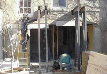
The plan called for four identical L-shaped steel braces — which cost about $675 each to fabricate — to be fastened to the brick wall from the backyard side, with each of the middle load-bearing columns receiving two equally spaced braces. Inserted 8 inches into the 12-inch-thick wall and positioned roughly 2 feet above the kitchen floor joists, the braces would support the exterior masonry wall without disturbing the kitchen wall. Each brace would be bolted to a footing so that it wouldn’t kick out from the load.
Because we felt that concrete footings formed on the surface also might kick out, we decided to bury the footings in the ground to help anchor them. We used a transit to verify that the top of each footing was level with the other.
While the concrete cured, we laid out the rough opening for the new door. On the left side of the new opening (as viewed from the backyard), we needed to remove a small window and close up the opening with brick. Another window located entirely within the rough opening would disappear after demolition for the new door. The window on the far right was a different story: It would be bisected by the rough opening, so we needed to remove it and brick over half the opening. We started our brickwork off the foundation wall and used brick ties on every other course to assure a strong connection between the new brick and the old.
To get the 400-pound braces into the backyard, we removed the sash from one of the garden-level front windows and passed each brace through, a task made easier by their L-shaped design. With the braces temporarily set into position on the footings, we marked their location on the faade. We were lucky that the top of each brace fell 1/2 inch below a mortar joint, which meant we’d need to do minimal shimming. Had the pocket height fallen within a brick, we might have had to shim the braces as much as 2 inches. In hindsight, it would have been better to have approximated the pocket locations before pouring the footings, chipped away the stucco to reveal the bricks and mortar joints, and then determined an optimal footing elevation with the help of a transit.