Back in 1979, when I first struck out on my own as a plumbing and heating contractor, I planned to offer my customers solar hot-water systems. But the oil shortages of the ’70s became the oil glut of the ’80s, and the tax incentives that helped give birth to the solar industry disappeared.
Subsequently, the industry suffered a quick and quiet death, a fact that hit home for me during a tour of a water-heater manufacturing facility in the mid-80s. In one corner of the plant, the solar division was sitting quietly — unoccupied — with everything just as it had been the day production stopped. It looked as if everyone had simply turned off the machinery and walked out the door. Crates of Taco circulators lined one wall, and flat-panel collectors — from bare frames to completed panels ready for delivery — lined another.
Now the tax incentives are back (see sidebar, “Tax Incentives for Solar”), the solar industry is thriving, and I’m determined to pick up where I left off nearly 30 years ago. To educate myself — so that I can offer my clients good systems suitable for our cold northeastern climate — I recently installed a Viessmann Vitosol 300 vacuum tube array (www.viessmann-us.com) on my own house in Pennsylvania. Vacuum tubes are more expensive than other types of solar collectors, but they can generate a considerable amount of hot water even in overcast conditions (see sidebar, “Does Solar Make Sense?”).
Tax Incentives for Solar States offer varying degrees of tax credit or rebate programs, which can help offset the initial investment of $5,000 to $12,000 for a standard solar hot-water installation. (For a complete listing of federal and state-by-state tax and rebate incentives, visit the Database of State Incentives for Renewables & Efficiency at www.dsireusa.org). The federal government’s tax incentive program can offset your investment by as much as 30 percent up to a maximum of $2,000 for qualified residential solar hot-water systems and an additional credit of equal value for solar photovoltaic systems. (Commercial installations do not have the $2,000 cap on tax credits.) To qualify for the federal or state tax credits or rebates, systems might need to be certified for performance by the nonprofit Solar Rating and Certification Corp. (www.solar-rating.org/) or a comparable entity endorsed by the state in which they are installed. |
Site Assessment
Good solar installations work best when they have an unobstructed view of the sun for at least six hours per day. My house has a significant amount of south-facing roof, but I still had to locate the collectors carefully to avoid late-afternoon shading.
Magnetic declination. To operate as efficiently as possible, an active solar system needs to face true (not magnetic) south. Magnetic declination — or deviation from magnetic north — can be easily determined for your location by visiting the National Geophysical Data Center’s magnetic declination calculator (www.ngdc.noaa.gov/seg/geomag/jsp/Declination.jsp). In our area, declination from true north is about 11 degrees west, so a south-facing roof (indicated by compass) is actually oriented 11 degrees east of south. If I’d installed a regular flat-plate collector and wanted to optimize its performance, I would have had to raise and pitch it 11 degrees west by adding an adjustable rack. One advantage of the vacuum-tube solar array is that each tube can simply be rotated to the proper orientation; you don’t need to tilt the whole array toward true south.
Tilting to latitude. Over the course of a year, the angle of the earth’s orientation to the sun’s rays changes. For average year-round solar gain, a solar array should be tilted above the horizontal at approximately the same angle as the latitude at which it is located. To maximize wintertime performance and decrease output in the summer months, the angle of the array can be increased by as much as 10 degrees from latitude.
My 9/12 roof has a 37-degree pitch, which is close enough to our 39.99-degree latitude that a flush installation is acceptable. As I add more collectors to the system, I may opt to mount them at a greater pitch than the roof to generate more wintertime Btu.
Tools. If you know a potential site’s southerly orientation, you can plot shading on graph paper or on a printed photograph — assuming the camera was held level — using a protractor and the sun’s angle, which can be ascertained at www.srrb.noaa.gov/highlights/sunrise/azel.html. Yet another — and more accurate — way to analyze a site’s solar potential is by using a Solar Pathfinder (www.solarpathfinder.com), a convex plastic dome calibrated to show the position of the sun each month of the year. When properly set up, the transparent dome will indicate exactly when — and by how much — that particular location will be shaded by neighboring trees and buildings, and even the structure’s own rooflines.
System Design
My system consists of a 30-vacuum-tube array with about 33 square feet of collector area. When sunlight shines on the system’s solar collectors, heat absorbed by copper-plate and tube assemblies within each evacuated glass tube turns the fluid sealed inside to steam vapor. This vapor rises into a condenser contained within the system’s double-pipe heat exchanger. Here, energy is transferred to a glycol-water medium, while the vapor condenses back into a fluid and flows (via gravity) back down into the vacuum tube to repeat the process.
When fluid temperatures in the collector’s heat exchanger exceed the water temperature in the storage tank, my system’s circulation pump is activated by a Vitosolic 200 differential temperature controller, which circulates the heat-transfer medium through a second heat-exchanger coil in the system’s storage tank.
One of the primary reasons I chose to install a Viessmann array is that its components are part of an integrated system, so there’s no need to mix and match individual pieces. For example, Viessmann’s Divicon pumping station includes not only a circulation pump, but also integrated fill and check valves, an air separator, a flow meter, and a pressure gauge.
Storage. My system is capable of generating 50 to 70 gallons of 140°F water per day; the actual amount varies depending on the weather and insolation (the amount of sun-energy available). To provide a storage buffer, I bumped the solar storage tank size up to 120 gallons.
Like most solar systems, this array is sized to provide about 70 percent of our anticipated yearly hot-water demand. A 75-gallon indirect tank provides additional storage and backup heat when the solar collectors can’t meet demand.
To keep the indirect tank topped off, a gravity hot-water recirculating system slowly moves water from the solar storage tank into the indirect tank, out through the home’s domestic hot-water loop, and back to the solar tank. Along with the extra storage capacity, this recirculation system has proven to be an excellent regulator that keeps tank temperatures below 190°F, even during extended spells of sunny weather and little system use.
A 1017/1016 thermostatic mixing valve certified by the American Society of Sanitary Engineering (ASSE) at the storage tank’s outlet limits outgoing delivery temperature to a maximum of 133°F. Faucets in all bathing modules are ASSE-certified 1016 scald-guard models set to limit hot water to 120°F.
Thermal protection. The transfer-medium fluid is a 50/50 mix of water and hydronic glycol, which won’t freeze. As with any hydronic system, I was careful to install the closed loop piping between the collectors and the storage tank so that there wouldn’t be any upside-down traps where air bubbles could form.
Since air bubbles trapped in the piping can halt flow and create steam, the system also has two air-elimination devices — one at the highest point in the loop and one in the mechanical room, between the circulation pump and the storage tank. Each consists of a stainless-steel screen housed in a body larger than the connected piping. Water flowing into the chamber slows a bit — like a stream entering a lake — giving the micro-bubbles a chance to collude, which means that they congregate into larger bubbles. The larger bubbles rise to the top and escape through an automatic air vent.
If a power outage or system malfunction should occur, fluid trapped in a solar array could quickly turn to steam, causing glycol degradation and allowing too much air to escape from the solution. To address this possibility, the solar thermal system has its own oversized 8-gallon thermal expansion tank. If steam does form — which would also increase system pressure and push fluid downward from the roof — the oversized expansion tank can accept the increase in volume. In addition, a pressure-relief valve piped to an atmospheric container (a plastic waste can with lid) captures any fluids so they can be re-used.
Backup power. In my area, we lose power about six times a year, with most outages lasting for less than an hour. Although no big deal for a refrigerator, these incidents can be problematic for a closed-loop solar system during peak solar-gain conditions: Stagnation can overheat the system and wreak havoc.
Since the differential sensor and low-watt circulator pump use only 33 watts of power, an inexpensive backup battery power pack (from www.apc.com) is sufficient for short-term outages. For longer periods, my system is tied into a 5-kw gas-powered generator that also keeps essential lighting, the refrigerator, and the heating and air-conditioning systems going.
Does Solar Make Sense? Because I plan to use my solar hot-water system to supplement my home’s existing hydronic radiant heating, I chose to install a vacuum-tube array. This type of collector produces hotter water under a wider variety of conditions than a flat-plate collector, making it better suited for the Northeast’s cold, cloudy conditions. However, a vacuum-tube array is more expensive than an equivalently sized flat-plate collector. My 30-tube vacuum array with about 40 square feet of collector area cost $3,830, while two of Viessmann’s 25 square-foot flat-plate collectors delivering roughly the same Btu output would cost $1,720. (View solar output ratings for other collectors at www.solar-rating.org.) In addition to buying the collector, I spent $2,000 on pumps, controls, and other hardware; Viessmann sells complete prepackaged systems ranging in price from $5,620 to $7,880. To see if the estimated $12,000 installed cost of my system could be financially justified (most solar hot-water systems will cost less), I completed a life-cycle cost analysis to compare it with fossil-fueled tank and tankless water heaters. For projected costs, I estimated a conservative increase of 5 percent for fuel, labor, and materials, and included replacement costs based on a 13-year life span for a tank-style water heater and a 20-year life span for a tankless heater. Over the 35-year estimated life span of my solar system, I calculated an average savings of $16,550. The payback for a solar thermal system can accrue in as few as six to 15 years, but the return on investment ranges between 9 percent and 49 percent, depending on the type and cost of fuel used by the conventional water heater in the comparison. Even without the environmental benefits gained by harnessing the sun’s power — or any of the federal and state subsidies now available — a solar hot-water system looks like a pretty sound investment to me. (For more on solar hot-water options, see “Solar Hot Water 101,” 10/05). |
Installation
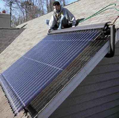
Because a vacuum-tube array can be disassembled, it is light and can be installed fairly easily by one person. And since the tubes aren’t filled with water, the unit isn’t heavy even when fully assembled and installed; most roofs can easily accommodate the load without any additional structural reinforcement.
One of the biggest challenges when installing one of these systems — particularly when retrofitting a new unit onto existing housing — is finding an inconspicuous route for the piping between the basement storage tank and the solar array on the roof. The easiest path often isn’t acceptable because it exposes the pipes to view. In our case, the only aesthetically acceptable route was through a series of floor joists that extended out over a concrete garage floor. This turned out to be the toughest portion of the entire installation.
System Performance
Our 120-gallon storage tank holds 1,000 pounds of water, so a 30°F gain in the tank equals 30,000 Btu gained (raising 1 pound of water 1°F requires 1 Btu; each 1°F rise in tank temperature = 1,000 Btu). With incoming cold water at 45°F, the system gains enough energy to heat 48 gallons to 120°F on a sunny winter day. Even with cloud cover in the winter, the vacuum-tube array captures between 2,000 and 20,000 Btu of solar energy per day. In the summer, the daily solar harvest passes the 50,000-Btu mark; the tank’s temperature climbs to an average of 160°F on sunny days.
With an anticipated life span of 35 to 45 years, the system will more than pay for itself, and we’ve significantly reduced our need for fossil fuels while eliminating tons of greenhouse-gas emissions. And it’s performed exactly as expected, with no maintenance required beyond my constant observing, probing, and poking to gauge its performance.
Dave Yates owns and operates F.W. Behler, a mechanical contracting firm in York, Pa.