I’m a stair builder in Michigan’s Upper Peninsula. My specialty is one-of-a-kind stairs, which I build in my millwork shop and then transport to the site for installation. This approach reduces travel expenses and greatly extends my working range. It also ensures that I get a professional-grade spray-booth finish that’s much nicer than I could ever apply on site. In late 2007 I received a call about replacing a curved staircase damaged in a fire. At first I wasn’t sure I wanted to look at the project; fire-repair work is messy, and I was concerned that the homeowners would want me to work within an existing footprint that was too small for a comfortable code-compliant stair.
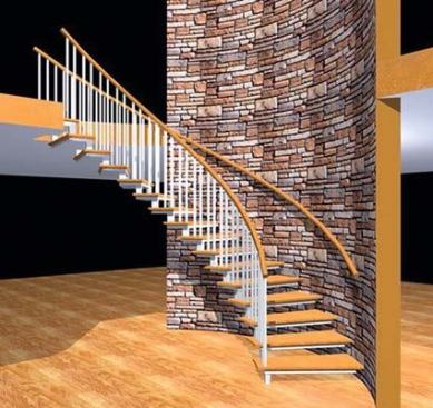
I needn’t have worried. The house turned out to be a total gut job, stripped to bare framing and primed white to seal in the smoke damage. And the owners were great customers — instead of telling me what they wanted, they asked what I envisioned in the space. The house was perfect for a design I had been thinking about: wood treads projecting out of a curved wall with no visible support at the outboard end. I gave the owners a CAD drawing and a description of how I would use a concealed steel frame to support wooden stairs, and they hired me to do the job.
We decided to build the stairs against a new curved wall framed to the edge of the opening for an existing basement stair. This wall — which would be clad in manufactured stone — would extend from the basement to the second-floor ceiling.
Templating
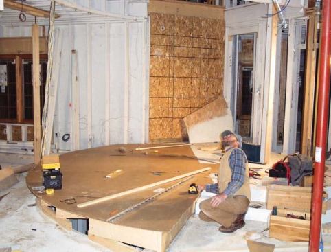
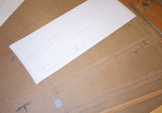
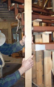
After building a temporary platform over the basement stair opening, I screwed down three sheets of 1/8-inch Masonite to create a full-scale template for the stairs. Then, using a level and laser plumb bob, I transferred the locations of key reference points to the template, including the balcony header, the edge of the second-floor platform, and points plumbed up from the arc of the existing stair opening.
Finding the center. Everything I built would be laid out from the center point of the opening in the floor. To find it, I drew chords between the points plumbed up from the existing opening, then drew perpendicular lines from the center points of the chords. The intersection of these lines was my center.
The template would have to make a number of trips between the shop and the site, so I marked the exact location of the screws securing it to the floor, then used the same screw holes every time I refastened it. In addition to the template, I made a story pole showing the vertical distance between the first floor, the raised foyer floor, and the top and bottom of the second floor.
Layout
Back at the shop, I marked the thickness of the finish-floor materials onto the story pole and divided the total rise into fourteen 75/8-inch risers. I then drew a plan view of the stair onto the master template.
The existing basement stair gave us our radii — 8 feet 9 inches at the outside and 5 feet at the inside. Subtracting the thickness of the manufactured-stone wall cladding left us with 42-inch-wide treads. There was sufficient distance between the balcony header and foyer landing for me to create an 11-inch run at the line of travel, 12 inches in from the center of the balusters.
The eight lower treads would cantilever from the wall; the five upper treads would be suspended between the balcony header and the cantilevered treads. Each tread would be supported by a tubular steel frame.
Structural Design
This wasn’t the first stair I’d supported with a hidden steel frame, but it was the largest, so I enlisted the help of the engineers at the fabrication company, UP Fabricating Co., in Rock, Mich. They helped me with the design, verified that it would work, and supplied steel components based on my drawings and cut list.
Main components. Among the parts provided were 2×4 box tube studs, curved plates for the wall, and tread frames made from 2×2 tubing. The tread assemblies would connect to each other with vertical riser bars made from 11/2-inch square bar drilled at one end to accept a baluster.
Wall Plates
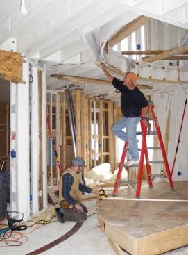
To lay out the curved wall, I installed multilayer plywood wall plates that I had made in the shop, aligning them with the plumb beam of a laser attached to a trammel. The laser beam was 8 feet 9 inches out from the pivot at the center point of the layout, so swinging the trammel caused the beams to describe the face of the wall.
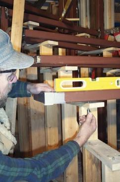
The plywood plates would provide nailing for the drywall and cement board to be installed on the wall. Once the top and bottom plywood plates were accurately positioned and fastened, we installed the curved steel plates over the plywood, through-bolting them to the floor framing. This gave us the surfaces onto which the iron studs would be welded.
Assembling the Frame
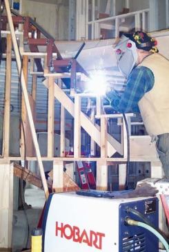
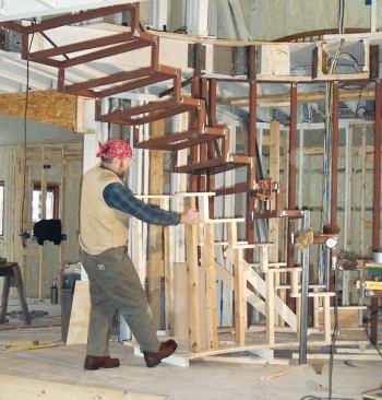
After installing the metal wall plates, I fastened the template to its original position on the floor so I could use it to locate the structural parts of the stair. The plan was to assemble the frame with tack welds and then complete the welds later on. To save time, I hired a certified welder to complete the welds.
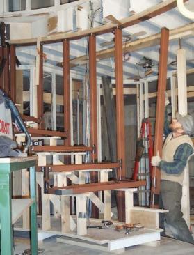
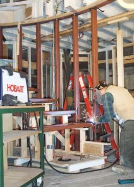
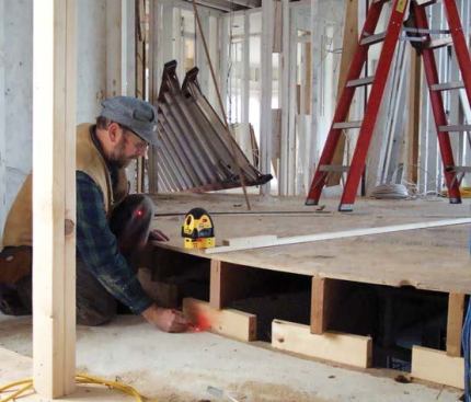
Temporary support. The tread assemblies came pre-assembled as three- and four-sided frames. With no stringers to orient the treads in space, I built a temporary wooden stage. This would support the treads while I positioned them over the template by plumbing up with a laser. To facilitate leveling, I threaded 1/4×20 bolts through the stage and used them to raise and lower the corners of the tread assemblies. Once the tread was in the correct position, I tack-welded it in place.
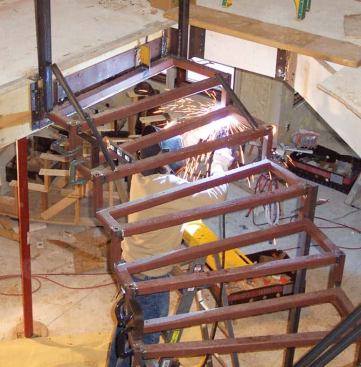
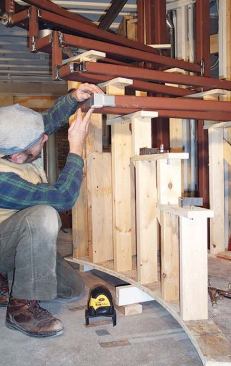
Top down. I installed treads from the top of the stair down. The first tread was welded to a plate bolted to the balcony header; each of the next four hung from a pair of riser bars — one bar at each end — connected to the tread above. From the sixth tread down, there was only one riser bar between treads because the inboard ends were welded to the 2×4 steel tubes in the wall. The tubes were welded top and bottom to the curved steel wall plates.
Welding technique. Welding suspended parts is unforgiving work; mistakes are cumulative and not easily corrected. Vertical, flat, and upside-down welds are all required and the heat generated has a tendency to warp and distort the joints. The key to avoiding this problem is to weld in short runs and alternate between opposite sides of the piece.
After each set of welds, I checked for alignment using the laser positioned on the floor template as well as an assortment of magnetic levels. Since much of the welding was done indoors, we used a 220-volt 180-amp MIG (metal inert gas) welder (Hobart Welders, 800/626-9420, hobartwelders.com) supplied with a mixture of CO2 and argon shielding gas, which reduces messiness by eliminating the need for flux. The 220-volt welder is good for thicker metal and has a longer duty-cycle time than a 110-volt machine.
Wall Cladding
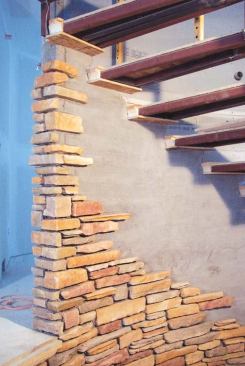
When the welder was finished, I installed temporary plywood treads on the frames and attached 2-by nailers to the tubes in the wall. Next, the drywall hangers installed cement board on the concave side of the wall as a substrate for the artificial stone.
To avoid scribing the wood tread covers to the irregular stone surface, I installed tread-shaped grounds where the tread assemblies would enter the wall. The masons butted their stone to the grounds — which, when removed, would leave openings into which I could tuck the treads.
Finished Parts
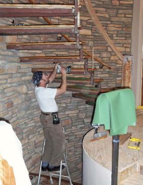
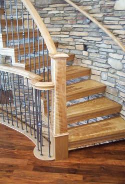
While the masons were installing stone, I was in the shop making the wood parts that would cover the steel core of the stair. Made from a combination of red and curly birch, the cladding was designed in such a way that I could finish the pieces in the shop and install them with the fewest exposed fasteners possible. I fastened the tops of the treads first, screwing in from the bottom through predrilled holes in the frames.
Balusters. Next, I installed metal balusters (part #40-602P) purchased from Custom Ornamental Iron Works (customiron works.com). At the front of each tread, the baluster passes through the wood and into a hole bored into the top of the riser bar. I tapped a second hole drilled in from the side to accept a set screw for locking the baluster in place. The rear balusters dropped into holes in the treads and were held in place with PL Premium Polyurethane Construction Adhesive (Henkel Corp., 800/999-8920, stickwithpl.com).
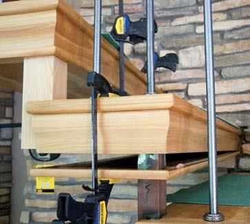
Tread cladding. Once the balusters were in place, we finished the treads by mitering a 23/16-inch-tall ogee nosing around the edges of the support frame and covering the bottom edge with 5/8-inch-thick curly birch. The miters were fastened with 23-gauge pins; other joints were biscuited and glued. I used the PL construction adhesive to attach prefabricated covers to the riser bars.
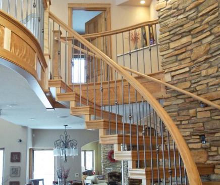
The remaining work involved installing the newels, rails, and balcony trim. Some of the components were curved and all were prefinished, but otherwise this part of the job was typical stair-building.
Proof of Strength
The completed stair is very stiff. One day I walked onto the job and found that the masons had set part of their staging on the outer edges of two treads near the center of the span. It was quite a shock to see two burly masons and hundreds of pounds of stone, staging, and mud creating a point load at one of the weakest parts of the stair. My concern was short-lived, though: A quick check with a level showed that the load had caused less than 1/16 inch of deflection.
Armin Gollannek owns Northern Sun Woodworks in Munising, Mich. The author begins the new set of stairs by building a temporary platform over the basement stair opening and transferring key locations onto a hardboard template. Here he uses a laser to plumb down the location of the balcony header. To find the center point of the curved basement stair opening, the author draws chords between points on the arc, then a line perpendicular to the center of each chord; where the lines intersect is the center point. After drawing a full-size layout of the stair on the template, he makes patterns of the steel tread assemblies and sends them to the fabricator. The curved bottom plate is located by plumbing down from a laser attached to a trammel that pivots off the center point. A carpenter shifts the position of the top plate so it’s in line with the beam that projects up from the laser . The author uses a temporary wooden stage to support tread frames while he positions them over the template. The block taped to the corner of this tread has the same cross section as a riser bar; its center is being used as the laser target. With the frame positioned horizontally in space, he checks its height against the story pole. He fine-tunes the height of the frame by turning threaded bolts in the stage. Once the frame is in the correct position, he connects it to the preceding tread frame by welding it to a vertical riser bar. Posts are installed between the top and bottom plates of the wall and then welded to the tread assemblies. Once all the pieces are connected together, the stage is removed and the welds are completed. Temporary wooden grounds space the stone off the tread assemblies. When the stonework is done and the grounds removed, the treads will slip into the recesses with no need for scribing. The tops of the treads are screwed to the frame from below, then the sides and bottoms are glued in place. The lower treads of the completed stair seem to grow out of the stone while the upper treads appear to hang in the air.


