To allow plenty of room for step-by-step photographs, we are running this article in two parts; the second part will appear next month. In this installment, the author shows how he lays out balusters, installs the landing newel, and accurately positions the railing and volute. In Part Two, he will explain how to make a gooseneck from stock fittings when the manufactured gooseneck doesn’t fit, and how to fit and install the volute newel and balusters. — The Editors
Over-the-post railings run continuously, starting at the bottom tread and stopping at the wall at the end of the landing on the floor above. The rail passes over pin-top newels so that your hand can run the full length without hitting a newel post.
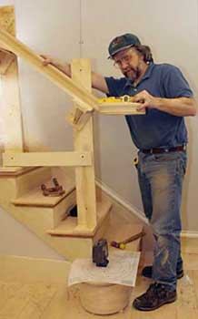
For this article, I built a full-dimension model staircase to explain a time-tested technique for building a traditional over-the-post balustrade using high-end manufactured parts. The rail system is assembled from straight rails and various fittings — such as volutes, easings, and goosenecks — that are generally obtainable through your local lumberyard. I recommend that you buy the best parts available, and then inspect them carefully before you start cutting. Reject parts with knots or checks, and don’t accept sapwood, mismatched grain, or obvious finger joints.
Rail Centerline Layout
There’s a classical, time-honored way to lay out balustrade parts, which I believe should always be the starting point for stair design: The front face of the first baluster on a tread should align with the face of the finished riser below, and the outside face of the baluster should line up flush with the face skirt below.
The centerline of the handrail is one-half the baluster width in from the face skirt. This maximizes the usable width of the stair and looks right because the corner of the baluster base appears to be an extension of the corner formed by the miter joint between the riser and the skirtboard.
To lay out the balusters, I mark the centerline at half the baluster thickness in from the face of the skirtboard and riser. You need to keep the centerline in mind when taking the first step in installing the balustrade — installing the upper-level landing newel. Contrary to many depictions of installed newels, which show the post installed entirely on the tread surface, half the landing newel’s thickness will stand proud of the face skirt and extend below its lower edge.


