Last year I got a call from a client who wanted to create more outdoor living space by building a deck along the back of her house over a part of the yard that was too steep to use. She said she wanted to use Trex, so I was picturing a conventional deck and guardrail. But when I stopped by her house — which was located in the hills above Oakland, Calif. — to look at the job, it became apparent that a conventional design was not going to work.
For one thing, the house had spectacular views of the bay and of San Francisco — views that a wood-picket guardrail would block. Therefore, I suggested using a glass or cable rail system.
Also, one end of the deck would lap onto an existing salt-finish concrete patio; in passing, the owner mentioned that she didn’t like the surface of the patio and wondered if it would be possible to cover it with the same composite material we used on the deck. I suggested covering the patio with stone tile instead, and when she said she liked that idea I proposed putting the same material on the deck, too; that way, the two surfaces would match.
By the end of our meeting, the client had agreed to have my company cover the existing patio with slate tile and build a slate-covered wood-framed deck with a glass guardrail system. The deck would be accessed from the patio, the existing kitchen door, and new French doors in the dining room wall.
Deck Structure
I would have preferred to build a freestanding deck and avoid having to deal with a ledger, but there was fill along the foundation so we couldn’t have installed piers there without digging deep holes. Normally we only have to excavate to undisturbed soil, because in this area the temperature almost never drops below freezing.
Our plan was to use a 4-by beam for the ledger, connect a portion of it to the house, and pick up the other end with a post on a concrete pier just beyond the end of the building. The framing at the other edges would land on posts, concrete piers, or the existing concrete patio.
Concrete piers. There were seven piers in all, each 2 feet square and about 15 inches thick, and each reinforced with four pieces of #4 rebar. Before placing the concrete, we positioned Simpson CB44HDG (hot-dip galvanized) column bases in the piers to hold the 4×4 posts. Since we were framing the deck with pressure-treated Douglas fir (ACQ) and the new chemicals are so corrosive, we made sure all the metal connectors were hot-dip galvanized or approved for use with ACQ.
Slope. Most decks slope away from the house so that water will drain off the outboard edge. But in this case the continuous glass rail presented a barrier, so we sloped the deck toward the house and allowed it to drain through a 3/4-inch space between the deck and wall. We installed a gutter below the deck to catch this water and direct it away from the foundation.
The slope presented a challenge because the structural glass-rail system needed to be in continuous contact with the perimeter beams. Sloping the end beam would have meant sloping the rail (which would look bad) or complicating the installation by requiring the glazing contractor to taper some of the glass panels. To avoid those scenarios, we installed the end beam level and allowed the joists to drop down from it at the end closest to the house. This created a small step at the bottom of one of the rails, which we later trimmed with strips of slate.
Framing Details
Since we wanted to retain an existing downspout from the roof, we blocked the 4×10 ledger beam an extra 3 1/2 inches off the wall to allow the downspout to pass through. We used LedgerLok screws (FastenMaster, 800/518-3569, www.fastenmaster.com) to attach two lengths of 4×10 to the back of the ledger, leaving a gap for the downspout.
Wall connection detail. The usual way to fasten a deck ledger is to bolt it to the rim joist of the house. But on this house the joists cantilevered a short distance beyond the foundation wall so that we couldn’t fasten to the rim, which was supported only by nails. Instead, we used Simpson HD2A hold-down hardware to attach the ledger to the floor joists beyond the rim — a connection detail similar to one an engineer had specified on an addition I’d built.
To gain access to the joists, we cut an opening through the stucco on the bottom side of the overhang; later we covered this opening with an access panel so that the connection could be inspected and maintained.
We staggered the bolts high and low through the beam and connected it at seven locations. Each hold-down was through-bolted to a joist and tied to the beam with 5/8-inch galvanized threaded rod.
To prevent leaks, we filled the holes through the stucco and the rim with Sikaflex-1a sealant (Sika Corp., 800/933-7452, www.sikaconstruction.com) before installing the rod. And to provide drainage we spaced the deck about 3/4 inch off the building by placing stacks of square 3-inch galvanized washers over the rods between the stucco and the ledger assembly.
Outboard edges. The left end of the deck lapped onto and was supported by the patio. We framed the two outboard edges of the deck with 4×12 beams, partly to support the load but also to make sure we had something solid to bolt the rail to.
We provided lateral strength by cross-bracing the end of the deck with 4×6 timbers. We installed them in line with the posts and beam because that method is stronger and looks better than lapping the pieces.
Joists and sheathing. Once the perimeter framing was in place, we installed 2×10 pressure-treated Douglas fir joists 16 inches on-center, blocked midspan and supported by Simpson ZMAX joist hangers. We then sheathed the deck with a double layer of 3/4-inch T&G pressure-treated plywood glued and nailed to the framing. The added layer provides the stiffness necessary to prevent natural stone tile from cracking. Had we been using ceramic tile, a single layer over our 16-inch joist spacing would have sufficed.
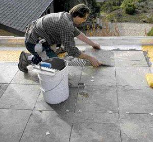
Crack-Isolation Membrane
An important aspect of this project was choosing a method to apply the stone that would reduce the likelihood of cracking caused by deflection or movement of the deck or slab. The proper way to do this is to install the stone (or tile) over a crack-isolation membrane. Also referred to as antifracture or uncoupling membranes, these materials are designed to reduce the amount of stress that can be transferred from the substrate to the finish. (For a list of available crack-isolation membranes, visit the Tile Council of North America Web site at www.tileusa.com)


