Our company does electrical and general contracting in Northern California. In 1999, customers started asking us to install standby generators because they were concerned that the upcoming Y2K event would lead to widespread power outages. We installed several units that year, found we liked doing it, and have since come to specialize in installing and maintaining standby power systems in homes and businesses.
A standby generator is permanently wired to the building’s electrical system. If the utility power goes down, an electronic control mechanism starts the generator and, after about 25 seconds, signals a transfer switch to disconnect the building from the grid and connect it to generator power. When the utility power comes back on, the transfer switch reconnects the house to the grid; after a short cool-down period, the generator turns off.
Choosing the Right System
Before we can install an electrical generator, we need to find out what the client expects the system to do.
Standby or prime? The first question we ask is whether the client plans to use the system for emergency use only (standby power) or on a regular basis (prime power). Most of our customers are looking for the former — a way to produce their own electricity on those rare occasions when the utility power is down. For these systems, we recommend generators that run on propane or natural gas.
But we’ve also installed power systems for people who live off the grid, by choice or because the house is so far back from the road the utility wants a lot of money to run power lines in. These customers usually want generators for prime-power uses, such as charging the backup batteries for solar- or wind-powered systems. In these cases, when the system is likely to run frequently or for long periods of time, we suggest diesel-powered units; they’re more durable and the manufacturers will warranty them for prime-power applications.
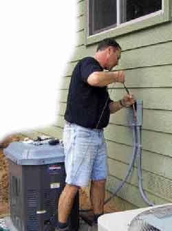
Under the HoodFrom the outside, a standby generator looks a lot like a central air-conditioning system’s compressor: It has a metal housing with access panels, openings for intake and exhaust, and pipes and wires going in and out. The housing contains an engine with a starting battery, an alternator, and — in some cases — a control system. Engine. Most residential standby generators take gaseous fuels — propane or natural gas. An engine run on propane will be 6 percent to 8 percent more efficient than one run on natural gas, so a generator rated for 13 kw on propane might produce only 12 kw on gas. Commercial generators and generators used for prime power usually have diesel engines. Most small gaseous fuel units are air-cooled. Diesel generators and some of the larger gaseous-fuel generators are water-cooled. Water-cooled generators last longer, can be run harder, and have a more consistent power curve than ones run on gaseous fuels. Before buying a generator, be sure to check that the manufacturer will warranty it for the intended application. Alternator. The generator’s engine drives an alternator, which in turn produces electricity. The alternators in standby systems come in two types: ones with two-pole rotors and ones with four-pole rotors. Residential systems generally have two-pole rotors, which produce electricity of a lower quality (meaning part of the sine wave is clipped off) than that provided by the utility. Though this is not a problem for most residential customers, it can be one for commercial customers who run large numbers of computer servers. We advise these customers to spend the extra money for a generator with a four-pole rotor. Generators with two-pole rotors run at 3,600 rpm and those with four-pole rotors at 1,800 rpm. People often ask whether the generator slows down under load; the answer is no. Generators must run very close to the specified rpm or they will not produce power with the correct voltage and hertz. The generator’s motor is controlled by a mechanical or electronic governor that maintains a constant speed by varying the amount of fuel fed to it. Behind the main access panel of this 15-kw unit (top) is a starting battery and a pair of breakers. The demand regulator on the lower right side of the unit opens and regulates the flow of gas to the motor. Gas reaches the generator by passing through a shutoff valve, a low pressure regulator, and a flexible hose (above). |
Whole or partial? We also need to find out the size of the house and whether the client expects the generator to power all or just some of the circuits. A whole-house system — one that powers all the circuits — costs more because it requires a larger generator and transfer switch than a partial system. Most people opt for a partial system that powers vital circuits, like the ones for the furnace, refrigerator, sump pump, well pump, freezer, and some of the lights.