
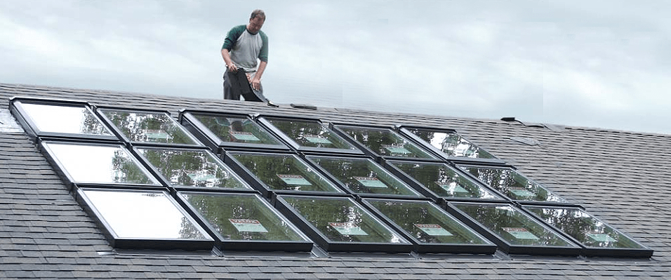
Last summer, a homeowner here on Cape Cod called to ask if I’d look at a large skylight he wanted to replace. The house — which he’d bought earlier that year — was an earth-sheltered, passive-solar structure dating from the late 1970s. On its south-facing roof was a site-built 12-by-16-foot skylight glazed with three layers of translucent, fiber-reinforced plastic sheets separated by stacked 2×4 framing (see photo below). It leaked, and the sheets had become too yellowed to see through. I was surprised it had lasted so long without blowing away.
My client, however, loved the dramatic size and the interior daylight. He wanted to replace the entire skylight area with manufactured roof windows, which would be both transparent and presumably more energy-efficient. I liked the idea and agreed to help design and install the replacement.
Layout and Framing
The unusual 70-inch-on-center truss spacing created three basic bays that I would need to subdivide into smaller mulled openings. The trusses measured 5 1/2 inches wide, leaving a 5-foot-4 1/2-inch space between them. I found that two Velux roof windows with a unit size of 30 9/16 inches wide by 46 1/4 inches high that would fit side-by-side between the trusses, with just enough room for a double rafter between them. In fact, the two units’ combined width of 61 1/8 inches left only 3 3/8 inches — not quite enough space for the framing and the recommended 1/4-inch rough-opening clearances. But because the units would be deck-mounted, not inserted into the openings, I figured I didn’t really need any wiggle room, provided the framing was meticulously square.
Referring to installation information on the Velux website, I drew a layout schematic. The final design contained a total of 18 windows — six across stacked three high, with alternating 3-inch and 6-inch spacing in between. Fortunately, the side-to-side “combi-application” flashing kits provided by Velux allow for spacing from 2 1/2 to 12 inches wide in 1/2-inch increments. Head-to-sill stacked spacing is restricted to 4 inches. Along the top and bottom, about 12 inches and 6 inches, respectively, are needed to accommodate the head and sill flashings.
Before providing a quote, my vendor faxed the drawing to the Velux distributor to verify my assumptions. In response we received a confirmed list of all the proprietary flashing components needed. In all, we’d be using 14 fixed units, four venting units, and a slew of proprietary flashing components, at a cost of just under $7,000. On delivery, we were buried in cardboard boxes.
After tearing out the old skylight, we found that the existing opening was within 1/8 inch of square — a great start. To ensure that the new framing would be accurate, I made story sticks showing the unit dimensions and the flashing spaces between them, one for the horizontal layout and one for the vertical layout.
We used 2x8s for the openings, to match the existing built-up insulated roof. The framing rested securely on the trusses and the exterior bearing wall below. After a couple of days of prep and framing, we were ready to install the skylights.
Installing the Units
On the ground, we prepped the units by removing the aluminum cladding as instructed and folding the installation brackets out from their shipping position. The bracket locations were already offset from one side to the other to avoid conflict when combining units. We snapped a chalk line square and parallel to the opening’s bottom edge and screwed the story stick down alongside it. The stick supported the first row of units and guided its placement. We started arbitrarily at the lower right corner and worked to the left.
The window package includes 1 1/4-inch annular-ring installation nails, but we used 2-inch-long #8 Fastap Plus screws instead. Screws are easier to remove when adjustments are needed, and they’re plenty strong. I cut plywood spacers to precisely control the flashing gap between units — 3 inches wide and 6 inches wide for the side-by-sides, and a set 4 inches wide for stacking the units vertically.
The installation manual requires roofing underlayment around the window frame, folded up from the roof onto the sides and wrapped in sequence from bottom to top around the four corners. We used self-adhesive membrane, beginning with Vycor in 6- and 9-inch-wide rolls. Between units, we had lots of three-way U-shaped folds to make. We scored the release paper on the back so we could bond first to the roof deck and then to the frames. But in the August heat, Vycor’s release paper tore away in annoying, uncontrolled strips. Picking at it only made the problem worse, rendering the product useless. Vycor is undoubtedly great when laid flat around a vertical window — the problem was in the folding.
We switched to 3-foot-wide ArmourGard Ice & Water Protector, which has a silicone-plastic backing that reliably peeled away in one piece. We cut it into the widths needed and scored the backing with a razor knife. Although thinner than Vycor and a little trickier to score without slitting all the way through, it worked like a charm, even in 90°F weather.
With the underlayment wrapped around the frames, we next installed the flashing, starting with the bottom aprons. There’s an integral rubber underglass gasket on the unit that must be pulled over the top of the apron’s rim. A slide-on clip engages the aprons’ upturned hems and makes a watertight connection between them. U-shaped aluminum channel flashing fits between units and overlaps the apron flashing by 6 inches. The channels are made for use with all models and, in our case, had to be cut to length. I used a plywood sled on the table saw, rotating the piece to cut one side at a time with a shallow-set 40-tooth ATB carbide blade. This made a clean, factory-grade cut.
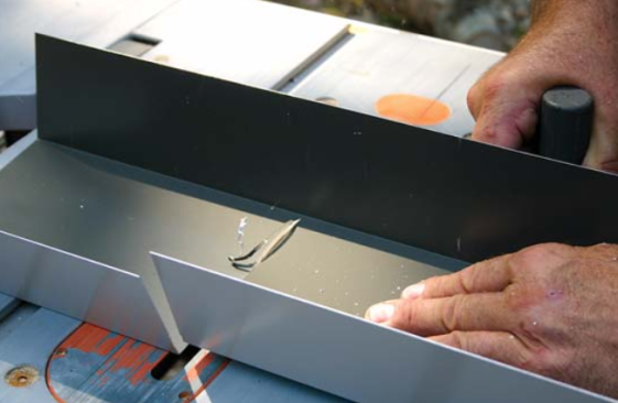
Cutting the flashing on the table saw prevents the distortion created by using snips.
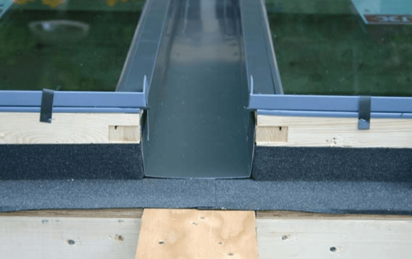
The channel gets cut flush with the heads and is then overlapped 6 inches by the combination head-sill flashing.
Tricky Access
We were able to install the bottom and middle rows by standing on the roof and on scaffolding set up inside. The vertical perimeter was easy to get to and we step-flashed and shingled as we went. But installing the field flashing was a bit of a challenge. To get access, we rigged up a sledlike scaffold that straddled the installed bottom row.
First, we stood 2×8 “runners” on edge on either side of the general area, running from top to bottom. We used12-inch-long hex-head TimberLok screws for anchoring the top ends into the roof framing. These screws helped prevent the boards from rolling over. For insurance we used two screws at the top end, about a foot apart.
The runners supported two 18-foot 2×12 planks spanning the windows. Above the truss locations, on top of the channel flashing, we slid shorter lengths of clean, smooth 2×8 under the planks from below, taking care not to scratch the flashing’s bronze finish or interfere with the head-flashing installation, which drops 6 inches below the heads. These intermediate supports broke the spans into sufficiently stiff 6-foot sections. We held them in place with 6-inch TimberLoks driven through the planks. The roof had a 6/12 slope, so it wasn’t too awkward to work from the planks; any steeper, though, and I’d have added some angled blocks to level the work surface.
We lined up the first middle window above the bottom corner window and used the 4-inch plywood spacers to stack them. The rest of the windows more or less fell into place with the spacers guiding their placement. After finishing the underlayment, we replaced the cladding pieces and installed the combination head-apron flashings. These fit quite snugly and needed to be forced into place with firm pressure. The flashing also trapped the rubber gasket against the frame; it took some finessing to fish out the gasket and place it over the top of the flange where it belongs. The head flashings interconnect the same way as the aprons, with a slide-on clamp.
There was one slight catch in the installation process. On each side of every head flashing is a dimple, intended for a wood screw that holds it down and against the frame. With only a 3-inch space between units and two layers of aluminum to punch through, I couldn’t think of any way to install those screws. Instead, I decided to hold the flashing down with 3/16-inch-by-1/2-inch aluminum rivets, drilled through a vertical fin that the flashing wraps over at the top of the unit. I knew the rivets wouldn’t compromise the flashing — but I also didn’t want to compromise the warranty, so I called the manufacturer’s rep, described the problem and my solution, and got the go-ahead. Since the rivets are just visible from the ground, we treated the 6-inch-wide channels the same way.
With the middle row completely flashed, we reset the scaffold for the top row. Initially, it seemed possible that we could install the windows by working from above, but a brief trial got rid of that notion — it was much too awkward and risky.
There were four venting units along the top row — one at each outside corner and two in the center truss bay. After installing four units using the plywood spacers as usual, we sighted a misalignment from down below, when we peered up the channels. This made no sense at first, but we found that, unlike the fixed windows, the venting units allow the frames to rack out of square. Good thing we used screws. We pulled three windows, realigned the first corner unit, and the rest went according to plan.
There was a masonry chimney to the left of the top row of windows, only about 12 inches away. I peeled back its lead flashing, wrapped the brick with underlayment just as we’d done with the roof windows, and tapped the lead back down. Roof shingles and 30-pound asphalt paper provide separation between the two flashings, in case aluminum and lead aren’t compatible.
Eight months and several cold, wet, windy storms later, the installation is leak-free. When the customer is ready, we’ll trim out the interior. Given the precise alignment between units, that job should go like clockwork.


