by Robert Viviano
One clear path to profit in any market is to develop a high-end, high-quality, and low-quantity niche. We started down this route back in 1989 when, to separate our company from deck builders who were pushing angles as the big option, we took the first steps toward becoming the “curved-deck specialist” of the greater Pittsburgh area.
We were on our own: Most of our competition didn’t want to be bothered with the additional work required to make curves. We now have a track record of building thousands of curved decks from cedar, ipe, aluminum, vinyl, and composite materials.
The key to building a profitable curved deck is to keep the construction as basic as possible. We design our curved decks to be almost as simple to build as angled decks by keeping the framing straight and square — it’s mostly the decking and railing that make up the curves. Here I explain the decking details. (Although some discussion of the railing layout is necessary, building the railing is beyond the scope of this article.)
Framing the Cantilever
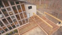
The curved deck shown (see photo above) has a semicircular cantilever extending 5 feet from the main deck. It’s framed with pressure-treated southern yellow pine, and the decking and railing are Trex.
No special treatment of the beam or its footings was required. The joists for the curving cantilever are simply longer versions of the common joists; they don’t require a second carrying beam but just cantilever farther out than the commons. This deck supports a roof as well, and two of the roof columns originate where the semicircle meets the straight part of the deck.
For any deck, the last thing you want is a cantilever that bounces like a springboard. Because 5 feet is a pretty large cantilever, we had the entire deck design engineered: 2×10 joists are spaced 12 inches on-center, and in the cantilevered portion every other joist is doubled. We don’t cut cantilevered joists to length initially but rather let them run long. A mitered six-section band board assembly will close off the cantilevered joists (Figure 1).
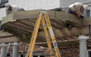
Figure 1. The mitered band board is first assembled and then installed as a unit. Blocks screwed to the bottom of the joists hold the band board in place while it's being installed. Note the doubling of every other joist.
We secure the joists to the house and the beam. Then we establish the center of the semicircle to provide a point of origin to lay out its arc. In this case, the center point is on the main part of the deck, set in from the edge by a distance equivalent to half the diameter of the porch columns and centered between them (see illustration, below).
Usually blocking must be installed between the joists so we have a place — other than air — to mark this point. If the center point did fall on a joist, we’d still block between that joist and its neighbors, to prevent movement and ensure accurate measurements.
The next step is to account for the railing. On the curved section, it will start at the porch roof columns and incorporate two 8-inch-square newels, which will be installed symmetrically around the curve. The band board will join with miters at the points where the newels will go. This will require a little calculator work. (see “Calculating Sides and Angles”).
Calculating Sides and AnglesIf you haven’t thought about circles and trigonometric functions since high school, don’t panic — these days you can use a calculator. Mine is a Texas Instruments TI-30Xa, which costs about $11. I have four of them, so there’s always one at hand. Since a circle contains 360 degrees, a semicircle — like this deck — contains half of that, or 180 degrees. A six-sided rim board works well with the substructure of a projection of this size (a 5-foot radius). Dividing 180 degrees by six yields equal pie-shaped sections of 30 degrees each (see illustration, below). Bisecting a 30-degree section provides two things: a right triangle (which enables use of the trig functions) and an angle (15 degrees) to plug into the formula. Toss in the radius (60 inches) and a calculator with trig functions, and you can quickly figure half the length of a side. Doubling that provides the total length, of course. Start with the basic formula for calculating the sine of an angle from the lengths of the opposite side and the hypotenuse of a right triangle: sin (A) = opposite ÷ hypotenuse Rearrange the formula to solve for the length of the side that’s opposite the inside angle: sin (A) x hypotenuse = opposite We know the angle is 15 degrees and the length of the hypotenuse is the same as the radius, which is 60 inches. Plugging those numbers into the calculator, we find that the opposite side measures 15.529 inches: 15 sin x 60 inches = 15.529 inches However, we bisected this side to make our right triangle, so we have to double the result to get the full length of the side: 15.529 inches x 2 = 31.058 inches, or roughly 31 1/16 inches The miter angle is half of 30 degrees. |
Once we figure out the miter angle (15 degrees), the number of boards (six), and the length of each board (31 1/16 inches), we cut the members of the band board and screw them together into a unit (Figure 2).
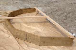
Figure 2. The lengths and miters of the band board's parts are ciphered on a calculator. To prevent the mitered band-board assembly from tweaking while it's being handled, 2×4 braces reinforce the desired shape.
We confirm the numbers by making sure the two ends measure 10 feet apart and the projection measures 5 feet from the miter points to the center point (Figure 3).
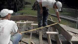
Figure 3. Always double-check the band board's size. The distance from the points of the miters to the center point of the curved section should be equal to the radius.
We use the assembled band board to lay out the cuts on the cantilevered joists. Our process is straightforward: Temporarily tack down spreaders to keep the joists on their centers. Overlay the band board so that its ends align correctly on the main deck (Figure 4). Scribe the inside of the band board to the joists and then move it aside.
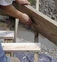
Figure 4. The cantilevered joists are purposely run long. The band board, aligned with the main deck, is placed atop the joists, which are then marked to be cut to length. Cleats nailed to the joists prevent them from moving and help to ensure accurate layout.
Next, extend those marks square down the joists and use a speed square to determine the angle of the saw cut for each joist (Figure 5). A couple of blocks screwed to the bottom of the joists support the band board during installation.
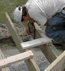
Figure 5. Mark the cut lines square down from the tops of the joists. The bevel angle for the saw is measured with a speed square from the marks atop the joists.
We don’t worry at this point about where the newels fall in relation to the cantilever joists. At worst, we’ll have to header off a joist or two to fit the newels later.
Finishing the Curve
If you don’t mind the look of the exposed band board, it can be considered completed at this point. If you want a curving fascia, however, you need to shim out the face of the band with curved 2-by material running horizontally at the top and bottom (Figure 6).
To create the shims, we take a 2-by that’s a little longer than the length of a side, hold it flat against the outside of one section of the band board, and scribe onto it an arc with a 5-foot radius.
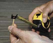
Figure 6. Curved shims are screwed to the band board to support a curved fascia (top). A tape measure hooked on the head of a screw (bottom) set at the center point is used to lay out the curve on one piece of 2-by, which is cut out carefully and used as a template for the rest.
To scribe an arc this big, we simply set a screw partway into the center point and hook the end of a tape measure to it. Then we hold a pencil at the tape’s 5-foot mark and swing away.
Mark this first piece carefully and cut it out using a good jigsaw with a sharp blade: Since all the sides are the same length, this piece becomes the template for the rest of the shims. Trace its curve onto the other lengths of 2-by, cut them out, and then screw all the shims in place.
PVC trim board (Azek is one example) will easily wrap around an arc of this radius. In fact, we’ve used Azek on arcs with radii as tight as 2 feet without heating it or kerfing the back. Other materials might require kerfing — you’ll probably have to experiment. Finding the length of the fascia board is a simple matter of measuring.
To protect the wooden fascia from streaking, we incorporate a standard aluminum drip edge between it and the decking (Figure 7). The back of the drip edge is notched with a series of Vs that allow it to curve. To seal the notches and to prevent the aluminum from contacting the corrosive pressure-treated frame, we install bituminous membrane or Grace Ice and Water Shield.
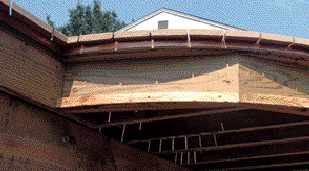
Figure 7. Notched to bend, an aluminum drip edge is installed below the decking to prevent streaking of the fascia. Bituminous roofing membrane on the joists prevents direct corrosive contact, and more membrane atop the drip edge seals the notches.
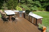
Fan Pattern
Any pattern of decking can be used on a curved deck. The trick is to let the boards run long and then cut them all off at one time. The decking here is cut into wedge shapes and fan-laid to radiate from the center point into the field decking (Figure 8).
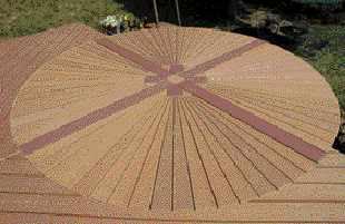
Figure 8. Wedge-shaped decking boards make up the fan pattern. Dividing the circle into quadrants with a cross pattern facilitates installation and creates a distinctive motif.
We add blocking where needed between the joists to support the decking and to allow the screws to run in concentric circles (Figure 9).
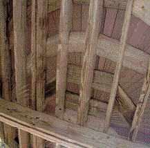
Figure 9. Some decking in the fan shape runs parallel to the joists, and the need for blocking to support it is obvious. Additional blocking allows the decking screws to be installed in concentric circles.
To figure out how many boards you’ll need for a simple decking circle, first calculate its circumference: Multiply pi (3.1416) by the circle’s diameter, including the distance that the decking overhangs the band board or fascia.
You want the deck boards to be as wide as possible at the outer edge of the circle, to minimize waste. The decking we use is 5 1/2 inches wide, plus we allow a 1/4-inch expansion gap, for a total of 5 3/4 inches. Using a calculator, we divide the circumference by this amount; for this deck the result was 68.02 — close enough to call it 68 pieces, each with an end width of 5 1/2 inches. (When the quotient isn’t a whole number, we it round up to the next whole number and divide the circumference by that number to find the end width for each piece.)
After we’d cut the wedges using these calculations, however, the customer asked for a change — to add even more visual interest. We came up with the cross pattern you see in the photos, which meant all the wedges needed to be recut to accommodate the cross.
Though adding it was extra work, the cross looks good and even offered up an installation advantage. It’s easy to spiral out of alignment if the wedges or your layout is off by even a hair. By breaking the circle into quadrants, the cross made it a little easier to control loss or gain.
Instead of using the center point of the circle as the starting point for the wedge layout, we used the inside corner of the cross in each quadrant as a pivot point. The width of each wedge on the inside of the circle is simply a point, and the length is equal to the radius of the framing plus the overhang and minus the centerpiece.
Because it’s important that the wedges be uniform and have straight edges, we use a jig to rip them (Figure 10). After cutting the wedges, we rout their sides with a round-over bit to match the factory edge.
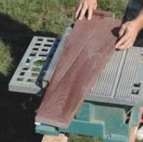
Figure 10. Straight-edged wedges require a jig. This is the sort of work where errors accumulate, so accuracy is called for from the start.
To save material, we try to cut overlapping wedges from the decking. We cut the pieces a little long so we can adjust them while we are installing them — we trim them after they’re installed. The pointy ends don’t need to be perfectly cut at first either, because they’ll be trimmed later to fit neatly around the centerpiece.
We use an installation jig to align the wedges radially (Figure 11). Essentially, it’s a piece of wood with a hole at one end that’s screwed to the center point on the deck. A “bulge” in the wood accommodates the screw, and the edge beyond the bulge is cut at an angle that mirrors that of the wedges.
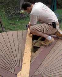
Figure 11. Another jig aligns the wedges radially. Cut to mirror the angle of the wedges, this second jig revolves on the center point.
The wedges are adjusted in and out slightly to keep the margins correct. Once a quadrant is laid out satisfactorily, we screw it down using markings on the edge of the installation jig to keep the screws in concentric circles: There’s nothing worse than a precise pattern with randomly placed screws.
To cut the ends to form a perfect circle, we affix a router to a long plywood arm, the bit at the correct distance from the center point. (Note that here I’m talking about the center point of the circle, not the corners of the cross.) The plywood arm is screwed to the center point, and the decking is cut off using a 1/4-inch up-spiral bit, which removes the material upward and out of the groove.
Don’t rush this part; it takes two to three passes, but it comes out dead-on. We cut inner and outer arcs by simply adjusting the pivot point on the plywood arm. After the edges are cut, we rout a round-over to match the factory edges.
The field decking is then laid to abut the circle. The ends are scribed with a compass, cut with a jigsaw, and rounded over with a router.
Robert Viviano owns Deck the Yards in Pittsburgh.