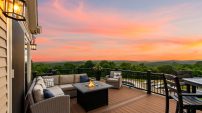
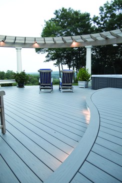
As a full-service remodeling firm, we work on many different types of complex projects and have gotten very good at designing, planning, and building methodically, while paying close attention to details. That was key to our success on this job, as we haven’t built a lot of decks and you can see for yourself that this deck — with multiple levels, curves, and a pergola, along with a screened-in porch — would have been a challenge even for more experienced deck builders. Working out nearly everything ahead of time, though, minimized surprises in the field and kept the project running smoothly.
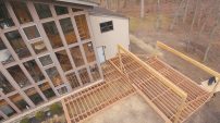
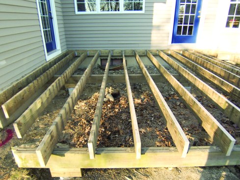
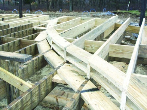
Planning started with a thorough survey of the existing deck. The 14-year-old pressure-treated deck boards were checked, split, and full of splinters, but since the joists and beams were in excellent condition (Figure 1), the ultimate design reused much of the existing structure. That meant we had to allocate significant time for power-planing the crowns in the old joists flat, because the PVC decking we were going to use would telegraph uneven joists and we didn’t want to end up with a wavy deck surface. In retrospect, it might have been more efficient to demo the old deck and start over — and it would have been nice to start new — but it would have cost significantly more for materials, plus demo, plus the time to reconstruct 700 square feet of sound deck framing.
Combining Loads Allowed for Fewer Footings
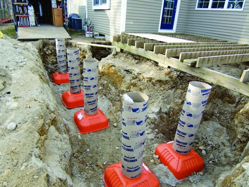
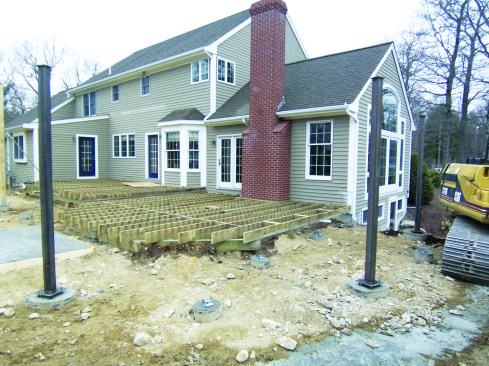
We designed the new deck beams to supplement the existing beams and footings and to provide support where the deck would be extended (Figure 2). The joists would cantilever past the beams and be trimmed to the radius later. The cantilever lengths varied, with the longest being just under 3 feet, which required both careful planning and some new footings.
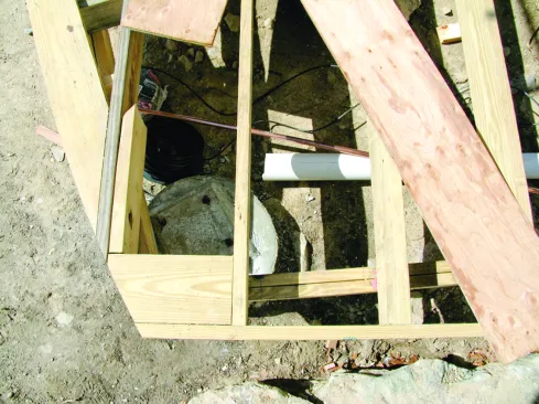
We looked at the project from two angles. The joists had to run in specific locations to surround the hot tub, form the curved steps, and carry the pergola posts. Those joists dictated the beam layout, which in turn dictated a footing layout. At the same time, footings to support the screen porch and the pergola posts had to be in particular locations. By combining loads and adjusting supports to rest on footings that had to be there anyway for another purpose, we were able to eliminate several footings from the design (Figure 3). The remaining footings were sized to carry the combined loads.
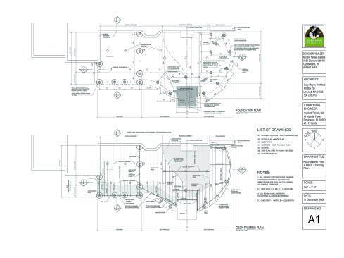
The plans for this deck were drawn on a computer (Figure 4). This was critical, because it allowed us to precisely locate the footings and radius centers — and that saved hours of head scratching in the field.
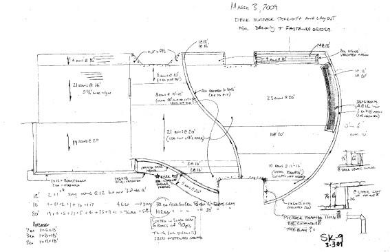
Calculating Material
One of the tougher aspects of building a curved deck is figuring out how much material it will require. If you don’t use detailed drawings, you’re at a serious disadvantage. I used a sketch during my takeoff and estimating process and literally counted every uplift anchor, every beam, each individual joist — and figured the layout and lengths of each piece of decking (Figure 5, page 32).
On a rectangular deck, it’s easy to figure that you need 40 joists at 16 feet. But on a curved deck, one joist could be 12 feet long and the next one 12 feet 9 inches and the next 13 feet 1 inch, and so on. When you order joists, too short is bad; too long and you have plenty of blocking. And believe me, we needed a lot of blocking on this deck. Round your lengths up. You’ll wonder where all your cutoffs went.
Figuring the decking for a rectangular deck is easy too. Depending on spacing, you might order 25 pieces of 5/4x6x16 for a 12-foot-by-16-foot deck, then add on for the picture frame and maybe some stairs. Voila, you’ve accurately ordered the decking in three minutes flat. But because the lengths vary on a curved deck, it’s a whole other ball game. For example, this 1,200-square-foot deck took about 2,560 linear feet of 5/4×6 decking. If I had ordered 128 20-foot-long boards and half of them had waste of between 2 feet and 3 feet, I’d have wasted 160 linear feet of decking. At $3 per linear foot for PVC decking, that’s nearly $500.
To avoid that loss, I had to find out what sizes the decking came in and do a detailed material-usage layout using a scale drawing. A carpenter’s first thought in minimizing waste may be to use the shortest piece possible, but truly efficient material use could mean using a longer piece whose cutoff can be used elsewhere. The drawing was essential in figuring this out.
For this deck, we had to bend material for the curved stairs and curved picture frame. To estimate the amount required, we needed to know the radius of the curve and the angle of the arc so we could calculate the length along a curve. This information was on the computer-drawn plans, and we used a Construction Master calculator for the math (see User Guide for Construction Master Pro, page 48, middle example, at calculated.com/ugfiles/UG4065408044080E-B.pdf).
Laying Out Curves
When it came time to dig the footings, all we had were plans and a few points of reference. One approach would have been to scale off the drawings, which for a simple round deck would probably have worked just fine. But that would never have worked for this project. For one, the windows and the screen and storm panels were ordered before a shovel hit the ground, so making adjustments was not an option. This is where those dimensions for the footing and radius centers on the drawings saved us hours.
Establishing the center of the lower deck radius was among the first things we did after the demo phase. It was the key to establishing the center lines of new footings for the pergola as well as the outside edge of the curve for that part of the deck. After finding the center of the pergola radius, we used a long board as a trammel to establish the arc. Then we located the four pergola column footings along that curve. They had to be exactly 72 degrees apart (Figure 6). Knowing the curve’s radius and the degrees of each “pie wedge” allowed us to use the Construction Master to figure out the point-to-point distance between the footings.
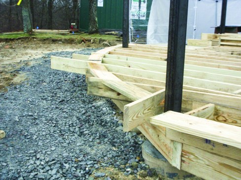
Installing the beams was straightforward. At the far right side of the large curved deck, where the beams ran nearly parallel with the joists, we put the footings and beams as far to the outside edge of the curve as possible (Figure 7). This allowed the last joist to be as close to the outside of the curve as possible (more later on why that was important).
The upper portion of the deck was more complex. It had a compound curve at the step down to the lower deck (Figure 8). The radius center of one part of the curve was somewhere inside the house, so it was impossible to swing an arc from that point, and the other center was in the yard. The curved stair at this part of the deck also had its center of radius outside the deck structure.
We could have set up pins or batterboards as fixed points from which to pull those arcs, but the centerpoints were in a very high traffic area and we knew they’d get whacked. Plus, they would need to be moved several times for other operations and have to be constantly reestablished. Instead, we made a series of templates by laying out plywood and drawing the roughly 14-foot-diameter arcs with a trammel. The templates were sized for the various radii of the face of the framing. To minimize waste, each template had two usable edges (inside edge and outside edge), so for four radii, we actually had only two templates.
Framing the Curve
We initially ran the joists long and later determined the location of the ends with a template or a drawn arc. Each joist had to be cut at a different angle, which was evident from the arc drawn on its end.
Before cutting the joists, though, we added blocking between the ends. The blocking serves three purposes. At the stairs, it’s a backer for the riser. It also provides continuous support for the curved picture frame and stair nosing, and it supports the butt ends of the decking boards, which run roughly perpendicular to the picture frame.
We ran the blocking long, like the joists, so we could cut the curve of the deck into it. This is where the curves of the deck really started to take shape. To locate the curve, we traced the templates onto the tops of the joists and drew plumb lines down both sides of each joist from the marks. We then numbered the joist bays, to keep track of which piece went where.
Next we laid a 2×8 across the top of the joists and traced the edge of the joists onto it. After numbering each segment (to match the bays), we cut the blocking along the scribe marks and made a duplicate for the lower blocking. The blocking was nailed flush with the top of the joists; we were careful to keep nails away from the edge of the curve marked on the joists. We set the lower blocking aside — it was numbered, too, so later on we’d know where it should go.
When all the upper blocks were in, we traced the curves with the templates. This gave a continuous line across all the blocking. We set a circular saw to just cut through the blocking along the curve. (You can easily cut curves to about a 10-foot radius with a single pass using a circular saw. Smaller radii will probably require two passes; you could switch to a jigsaw, but a jigsaw takes forever because you’re cutting with the grain.)
Next we laid the lower blocks directly over the upper blocks and traced the curve; one person cut them all while another got busy with a reciprocating saw cutting off the joist tails. Then we installed the lower blocking, making sure its face was plumb with the blocking above it.
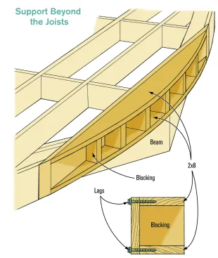
At one point — because of the curve, the beam location, and the joists running nearly tangent to the curve — blocking had to support the decking all on its own (Figure 9).
Here we lagged 2x8s parallel to the outer joist but oriented on the flat. We lagged one 2-by flush with the top of the beam and another flush with the bottom. The lags went into the edge of the blocking through the back of the joist. Then we added vertical blocks perpendicular to the joist as structural spacers between the “on flat” 2x8s. This is what carries the right edge of the curved decking. It’s a fine solution for this area, where no one can stand because of a fixed bench, but I’m not sure I’d love it for a high-traffic area like a step. If that had been the case, I’d have looked at framing this differently.
Bending the Decking
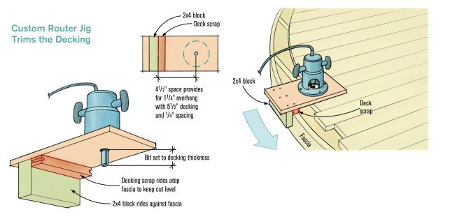
Installing the decking went much as it would on any deck — we started at the house and worked toward the outside edge. This deck required a decorative picture frame, so we had a couple of extra steps. We wanted a 11⁄4-inch overhang beyond the 3⁄4-inch riser on the stair and the fascia on the deck. With a deck-board width of 51⁄2 inches plus a 1⁄4-inch gap, that meant we had to cut the field boards 41⁄2 inches back from the face of the riser. Knowing that, we had kept all fasteners at least 4 inches back from the face of the framing. We made a simple router guide (Figure 10, page 38) to accurately cut back the decking parallel to the riser.
Once all the straight decking was installed, we installed the Versatex risers and fascia (Wolfpac Technologies; 724/857-1111, versatex.com). They faired out the little lumps and bumps in the blocking and provided a smooth surface for the guide to ride against. We finished the decking ends off with a 1⁄8-inch round-over bit to match the other decking edges.
To bend the picture frames, we used a pair of HC99-300 Heat Forming kits (Heatcon; 800/556-1990, heatcon.com). At $1,500 each, these kits aren’t cheap, but they do the trick nicely. Each kit comes with two 10-foot-long heating pads, so to heat a 20-foot board, you need two kits. Essentially, you make a sandwich out of a single piece of decking (the meat) and two silicone heat mats (the bread). Surround that assembly with some R-38 insulation and then monitor the temperature through the programmable controllers until it gets just hot enough to bend. Then it’s a fire drill getting the decking onto your form before it cools.
Kim Katwijk has a good video on YouTube that shows this process (youtube.com/watch?v=oMVvjL8yQmY&feature=related). Kim makes it look easy. It isn’t. We ruined a lot of $60 boards on our way to moderate proficiency with this expensive tool. I guarantee you’ll do the same.
The very soft, heated decking needs a solid substrate to support it, which is one reason for the blocking: Voids in the framing will let the boards sag, and they’ll stay that way. It takes at least two people to move the boards; we used three and four people to more evenly support the soft boards and were glad we did. It’s easy to deform them, and they don’t easily go back to the shape you want if damaged.
The boards swell, so count on them ending up about 1⁄16 inch thicker than unheated boards. We also found that the end of the curve doesn’t curve quite as much as the center. Use boards longer than you need and cut off the ends once the material cools.
We used two methods to hold boards in place until they cooled. For the stair treads, we temporarily screwed plywood to the stringers that extended far enough so we could screw down blocks to hold the hot, soft boards in place until they cooled. The picture frames required a more expedient but less effective approach. Because those boards extend beyond any support, we had to screw them in place right away, stopping the screws just as they began to dimple the board. We could have used a temporary support, as with the treads, but that’s a lot of work for one board. After the boards cooled, we removed them to trim their ends. While we used TC-G hidden fasteners (Tiger Claw, 877/873-2529, deckfastener.com) on the rest of the deck, they wouldn’t work on the curved boards. Those we drilled for Cortex screws and plugs (FastenMaster; 800/518-3569, fastenmaster.com).
In Retrospect
From the standpoint of building for generations, I don’t like all that flat blocking. It could hold water and encourage rot. Next time I’d cover it with a butyl-based adhesive membrane (asphalt adhesives and PVC don’t play well together). For that matter, membrane over all the joists would be a great idea as well.
The time spent on scheduling, layout, and calculations meant few problems in the field and efficient use of our crew. Lack of preparation would have turned this project into a big headache and a financial loss for our company. Just the time taken to test different deck fastening systems probably saved us 30 man-hours — which we would have spent had we used a more difficult fastening system (we installed nearly 1,000 deck clips).
Joe Cracco, CGR, CAPS, CGP, is the Big Cheese and Manual Laborer at Modern Yankee Builders, in Cumberland, R.I.
Editor’s note: For a look at what went into building the impressive pergola on this deck, see Day’s End, “Floating a Pergola in Place” (July/August 2009) and PDBWeb Exclusive, “Complex Pergola Details,” both free online at deckmagazine.com.