Foundation styles are now sized according to bearing area and an…
Originally published in 2007, the American Wood Council’s (AWC) Prescriptive Residential Wood Deck Construction Guide—commonly referred to as DCA 6—is a recognized resource for both deck builders and code administrators. It was updated to conform to the 2009 IRC, and this summer, it was updated again to reflect requirements in the 2012 IRC and to more comprehensively address a deck’s load path. In this article, I’ll review the biggest changes in the 2012 DCA 6, following the load path from the ground up. (A free PDF of DCA 6 can be downloaded here.)
Foundations
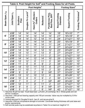
Deck foundations range from shallow and broad footings to deep and narrow piers, depending on frost depth, soil type, and local practices, so any attempt to standardize them is complicated. The IRC and DCA 6 size footings based on bearing area (the area of the bottom of the foundation that’s in contact with the earth). Applying their provisions using the lowest standardized soil bearing capacity (1,500 psf) yields large bearing areas that work well for shallow and broad footings, but not for deep and narrow ones. Regions of the country that have been getting by with 8- to 12-inch-diameter piers, 30 inches or more in depth, may be surprised by the new DCA 6’s 18-inch minimum diameter—up from 15 inches. Smaller-diameter footings are still allowed in soils with a bearing capacity that is known to be higher, such as sand or gravel.
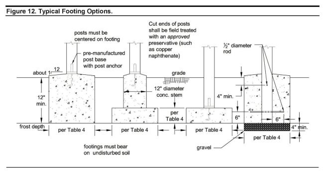
The 2012 DCA 6 also includes the weight of the concrete foundation itself in calculations. New illustrations show various common footing methods, but the sizes are still based on the bearing area of a shallow footer (Figure 1). For instance, if an 18-inch-diameter pier is poured deeper than the minimum 7 inches provided in the table, then the weight of the additional concrete should be accounted for in adjustment factors provided in the commentary, yielding an even larger pier diameter. To offset this condition and reduce the amount of exposed concrete at the top, a pier/footing foundation with a narrower pier bearing on a larger footing can be installed.
A new footnote allows for a reduction in footing size for a corner post, which is assumed to be carrying half the weight of a mid-span post. The reduction is 10%, though, not 50%, to account for lateral loads acting on the corner posts through knee braces.
Posts
Previously, DCA 6 had a blanket maximum post height of 14 feet. Now, maximum height—newly added to the foundation table—is based on joist and beam spans and the species of lumber. Also, research showing that lateral loads on the deck are translated to lateral forces on the posts through knee braces has resulted in a reduction of maximum post heights, now between 2 feet and 14 feet. To ease design constraints caused by this change, the document allows the use of 8×8 posts up to a 14-foot height for all conditions in the table. As in the past edition, the commentary provides some methodology for using 4×4 posts, such as on small stair landings.
Preservative Treatment
In previous DCA 6 editions, various wood species were listed in Table 1, along with the minimum required ground-contact treatment retention required for common preservatives. Though useful to the technical reader, it has been replaced with a table that simply lists which species can be treated for ground contact and which can’t.
Glued Laminated Beams
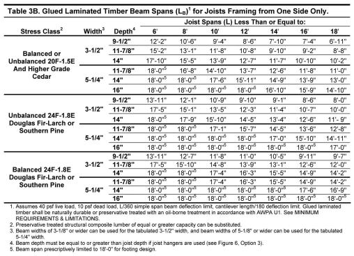
One of the most helpful parts of DCA 6 is its table of deck beam spans based on joist span (so helpful that a similar table has been added to the 2015 IRC). The new version improves on that by including a table for glued laminated timbers, or glulams (Figure 2), which not only accommodates different architecture, but also allows for up to an 18-foot span—up from 15 feet for a three-ply 2×12 in the previous document. (Though glulams can certainly span farther than 18 feet, the span is limited here by DCA 6’s foundation design.)
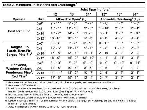
2×6 Joists
Sometimes a deck—one at ground level, for instance—is best served by the low profile of 2×6 framing. Though overlooked by previous editions, 2×6 joists are included in the new DCA 6. While this adds design flexibility, a minimum 2×8 must still be used for attachment of a guard post.
Cantilevers (or Overhangs)
The new DCA 6 has revamped the manner in which the allowable joist span and overhang interact (Figure 3). As the overhang is increased, the maximum span is typically decreased to account for the extra loads. The AWC recognized that this phenomenon creates real headaches for a prescriptive design approach, and decided to present the limitations in a different way in the new edition.
In simple terms, previous editions limited span based on maximum overhang, whereas the new edition limits overhang based on maximum span. Previously, the joist span table was divided in two: joist spans with overhangs and joist spans without overhangs. Joists were allowed to overhang up to one-fourth a reduced backspan. However, even a slight overhang, perhaps 6 inches, would trigger a significant reduction in allowable span.
The new presentation is meant to be more flexible and better apply to the actual loads of each design. Only one maximum span is provided, and the other half of the table provides the maximum overhang for each condition. Note that it’s not always one-fourth the backspan; and though there’s still a footnote limiting overhangs to one-fourth the backspan, it’s secondary to the maximum allowable overhang for specific conditions.
Hollow Masonry
The 2009 DCA 6 included a figure specific to connecting a ledger to hollow masonry that required the cells at anchor locations to be filled with grout or concrete. Because the detail works only for new construction, the AWC eliminated the figure; however, the option remains as a note in the solid-masonry figure.
Hold-Down Tension Devices
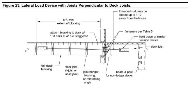
The 2012 IRC clarified that decks must resist lateral loads, and that the detail in figure R507.2.3 is a permitted—though not required—option. Researchers at Washington State University continue to examine the role of hold-down tension devices and the lateral load path on decks as a whole; their findings could eventually lead to changes in the currently permitted method. In the meantime, the AWC uses the IRC’s prescriptive approach, which requires at least two hold-down tension devices for all decks.
Expanding on the IRC detail, DCA 6 offers methods for installing hold-downs to various floor configurations. New figures provide options for connections to house floors that are built with engineered I-joists and solid joists in both parallel and perpendicular orientations (Figure 4). When floor joists are parallel to deck joists, connections must be made to a 3-foot-long 2×6 attached to the I-joist web with 16 clinched nails. When deck joists are perpendicular to interior I-joists, blocking must be installed 6 feet into the floor and connected to the sheathing 19 times. Similar to details produced by the Wood I-Joist Manufacturers Association for new construction, these connections won’t be easy to install in existing construction where there is finished space below the interior floor. The IRC load target of 1,500 lb. in a concentrated location (nearly the curb weight of a new Smart car) is quite a load to design for, so the connection details are intended to distribute the load across the entire floor diaphragm as opposed to on a single joist.
Also new to the 2012 edition is an allowance for the threaded rod to slope up to 1:12 away from the house.
Aspect Ratio
Regardless of how many hold-down tension devices are installed on a deck, there’s another lateral load issue that is not addressed in the IRC: Without braced walls and floor diaphragms, what keeps a deck from swaying?
The AWC analyzed lateral loads that act over a deck surface and included them in its design assumptions for knee braces and corner post height. Since center posts are not designed for the added lateral force applied by knee braces, bracing can be installed only at corner posts. But the ratio of a deck’s length to its width, or its aspect ratio, also affects overall lateral loads—much like a longer wrench will place more force on a bolt. Therefore, DCA 6 sets a limit: The aspect ratio must be no more than 1 to 1; that is, a deck cannot extend perpendicularly from the ledger more than the length of the ledger. Commentary for the document, anticipated by the end of 2014, will allow for a 1:1.5 ratio when angled decking is installed.
Glenn Mathewson is a building inspector in Westminster, Colo., and a private code educator and consultant. Tables and illustrations are reproduced with permission of the American Wood Council, Leesburg, Va.