Bracing Walls for Wind: Calculating the Required Length of Bracing
3 MIN READ
The amount of bracing required is a function of the wind speed, the exposure, the story of the house, the spacing of the braced wall lines, and the bracing method used. In his training course, Foley teaches a method for calculating the required bracing length that he calls “Choose it, Adjust it, Compare it.”
- Choose it. Select required amount from Table R602.10.3(1).
- Adjust it. Multiply by adjustment factors.
- Compare it. Actual BWP length must be greater than the required BWP length.
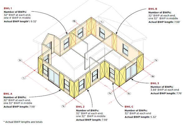
In the three examples below, we use Foley’s method to find the required bracing for the first floor of the example house shown.
Step 1: Locate the braced wall lines (BWLs) on the plans. Remember, BWLs do not have to line up with actual walls. In this example, BWL 1 accommodates a few walls that are all within the 4′ maximum offset.
Step 2: Determine the spacing between the braced wall lines. The spacing is shown in column 1 of the results table. See “Calculating Average Spacing,” for a breakdown of how the BWL spacing was calculated.
Step 3: Look up the required bracing length in Table R602.10.3(1). Note that the results we list in column 2 of the chart in Example 1 are “interpolated” values: Because our actual spacing falls in between the spacing increments in Table R602.10.3(1), we calculated a number that lies proportionately between values in the Methods CS-WSP column.
Step 4: Adjust the required bracing using the appropriate adjustment factors. In Example 1, the house is located on an Exposure B site (no adjustment needed); the first-floor walls are 8 feet high (earning a slight credit of 0.9); and we have three BWLs running in the same direction both ways (requiring an adjustment of 1.3 to each BWL). The adjusted bracing length (last column) is reflected in the braced wall panels shown on the house.
[Note: To make these calculations using an interactive spreadsheet, search for “wind-bracing” at fairfaxcounty.gov.]
Example 1
This base case assumes that the sample house is in Exposure B, with 8-foot walls and a shallow-pitched (3/12) intersecting roof. The adjusted BWP length is the result of multiplying the “Required bracing length” successively by each value in the four “Adjustment Factors” columns. For example, in the top line of the table at right, 8.1 x 1 x 0.85 x 0.9 x 1.3 = 8.06; the “Actual BWP length” takes oncenter framing into account.
Example 2
In this example, we are exploring what happens to the same house if we relocate it on a more exposed site (Exposure C), raise the first-floor wall height to 11 feet, and make the intersecting gable roof steeper. The table lists the changes, and the illustration above graphically shows the reduction in the wall space available for windows and doors.
Example 3
To make room for more windows and doors, we can extend BWL C and add BWL 4, which adds bracing on three interior walls. But we must include let-in metal bracing (“Method LIB” in Table R602.10.3[1]) in these interior walls before hanging drywall, then fasten the drywall to the required “GB” schedule. The location and building features for Example 3 are the same as in Example 2, but the distances between BWLs are shorter, reducing the required bracing lengths. We pick up a slight penalty for adding BWL 4, but compared with Example 2, we reduce the amount of bracing required, allowing us to return to the Example 1 window and door layout, except for one less window along BWL A.


