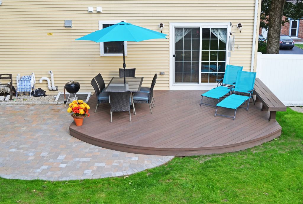
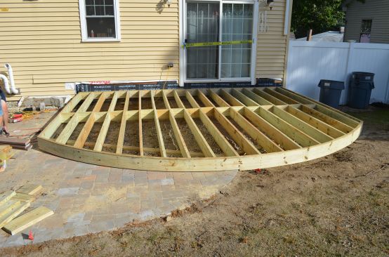
Our customer’s requirements were simple: Build an interesting deck and patio off the back of the house. The deck would be low enough to make rails unnecessary. We recommended curves, and the customer liked our simple, elegant design.
Building the patio was straightforward, but building the deck became challenging. Here in New England, we like to set the height of our decks one riser below the interior floor (a step down of 6 to 7 1/2 inches), to help keep rain and snow out of the house. The area for our 15-by-17-foot deck was mostly flat and about 14 1/2 inches below the kitchen floor. So we would set the deck 6 inches below the floor, leaving 8 1/2 inches for the deck. Fitting the entire structure of a curved deck within 8 1/2 vertical inches, however, is difficult.
Double-band construction, using joists attached with hangers to a double rim, would require the least height. But that posed several challenges. To start with, the distance from the house to the girder at the front would be too great for 2×8 joists to span. So we would need to frame the deck with 2×10 joists; but those would not fit into our 8 1/2-inch-high space. Should we dig out and remove a few inches of soil over the entire area?
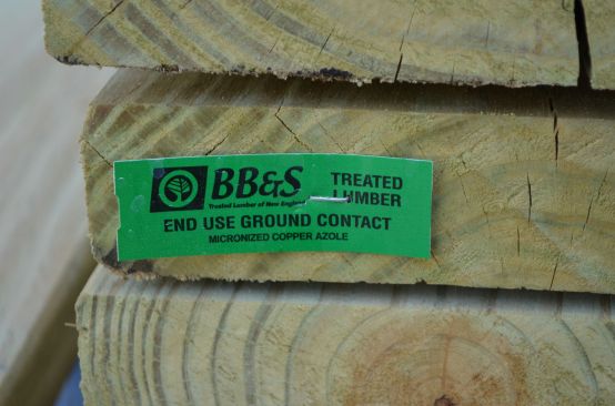
Another challenge was that, in order to support the joists, the curved rim would need to be doubled. But how could we bend a double rim? Vertical relief cuts (like the cuts shown on page 54) would weaken this structural member too much. Laminating two 1x8s together with glue and nails would create a strong enough member, but setting the correct curve would be difficult. In any case, it was not feasible, because 1x8s were not available with the necessary ground-contact-rated preservative treatment. Finally, even if we could solve those issues and build a suitable curved structural rim joist, the footings to carry that member would have to lie directly under the front of the deck and would actually define the deck’s curved edge. Their placement would have to be precise.
Post and Beam Construction
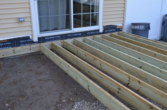
So, instead of a curved structural rim joist, we opted for post-and-beam framing. We would locate a carrying beam about 2 feet back from the deck’s front edge, under the joists. This configuration gave us two major advantages: First, it reduced the joist span so that 2×8 joists would be able to carry the load; and second, it allowed the joists to cantilever past the beam, which would make shaping the curve much easier.
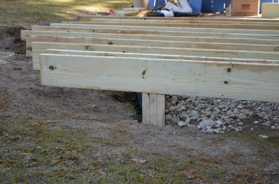
Post and beam did impose one disadvantage, however: Because the structure of joists on top of a beam would occupy 16 1/2 vertical inches, the beam would need to be set into the ground, with its top just about at grade level. We’d have to dig a fairly deep trench to accommodate the beam, with a drainage space around it. But that work was worth doing, because it would separate the rough work of installing footings from the fussy work of finishing the precise, symmetric curve. We’d rather trim a half-inch off the end of a joist than have to adjust the location of a footing 4 feet deep in rocky ground.
We drew detailed structural plans and calculated weight loads so we could size the beam and joists properly. Although our building code (IRC 2009) requires a 40-pound-per-square-foot (psf) live load for decks, we build all our decks to 60 psf. I still remember when the extreme snow in February 2015 accumulated more than 4 feet deep in the Boston suburbs. That much snow can indeed weigh 60 pounds per square foot.
Our design imposes a load of 429 to 595 pounds per linear foot (plf) along the angled beams. Over the 6-foot-3-inch spans between footings, we could have used double 2×10 beams; but triple 2×8 beams could support even more weight and saved us 2 inches of digging.
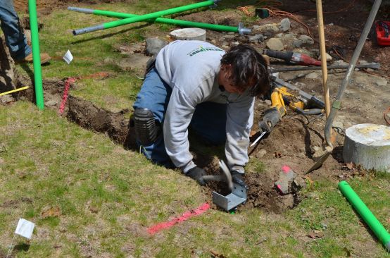
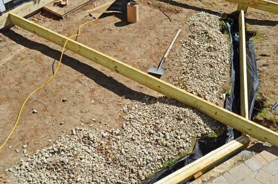
Trenching a beam requires more than just digging a long hole. The beam needs space underneath to prevent frost from pushing it up in winter. Over time, dirt would fill in that space, so we over-dug the trench, lined it with landscape cloth, and surrounded our below-grade beam with loose, clean stones. Those stones drain well and will move aside if frost threatens the beam. The landscape cloth prevents soil from infilling the spaces between the small stones.
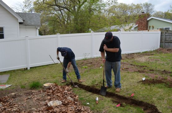
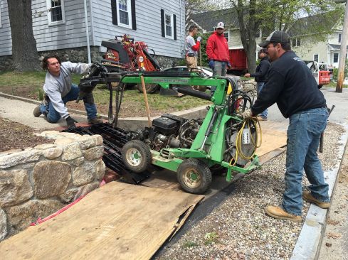
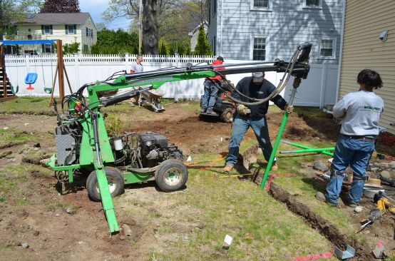
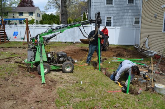
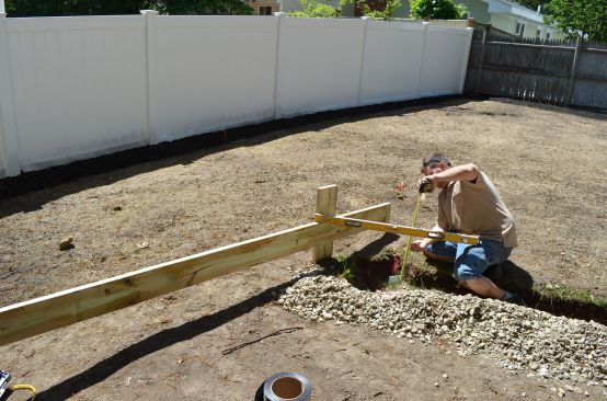
Footings
For the deck footings, we could have used concrete poured into Sonotube forms, but that method would impose two difficulties here. Digging for the tubes would be dangerous so close to the patio, and properly compacting the soil around the 4-foot-deep piers was not feasible: Soil would settle over time and cause the adjacent patio to sink. Instead, we used helical footings—long galvanized pipes with a large screw at the end. A hydraulic machine twists them into the ground without disturbing the surrounding soil, and the machine’s torque gauge tells us when the required bearing capacity has been achieved. We twisted each 7-foot helical footing into the ground below the frostline, and cut the end off once it exceeded the required bearing capacity. We then attached adjustable brackets to support our beam.
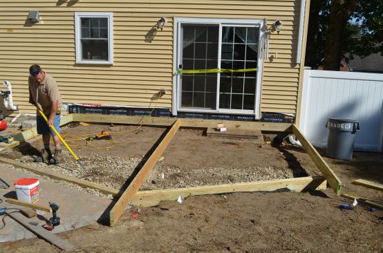
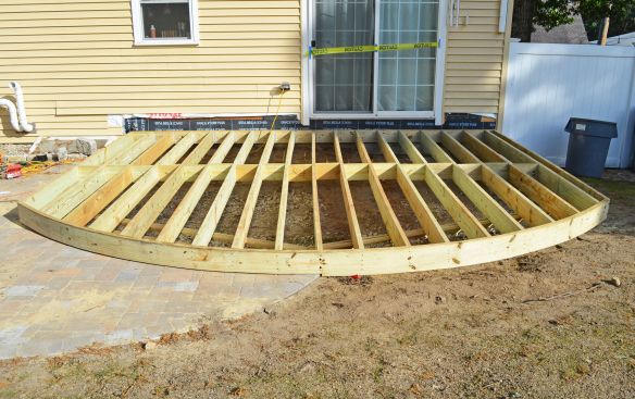
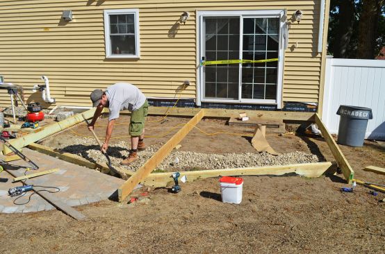
Framing
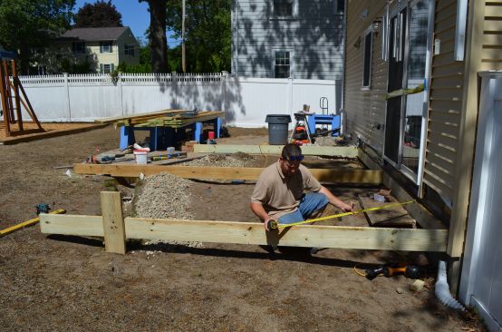
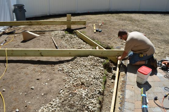
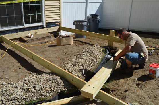
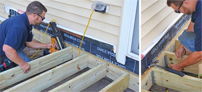
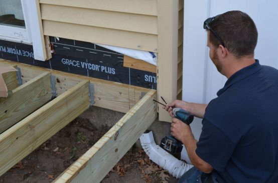
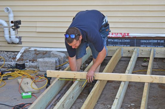
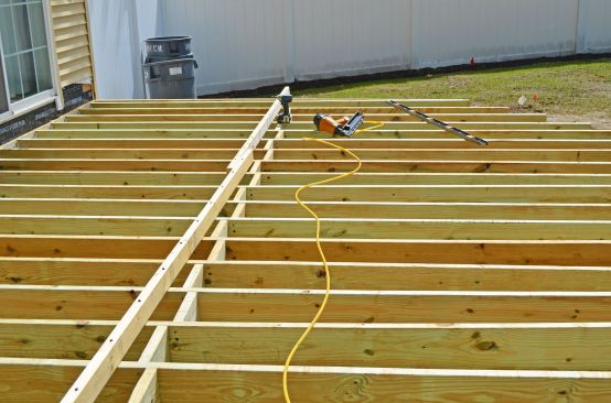
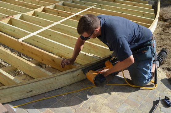
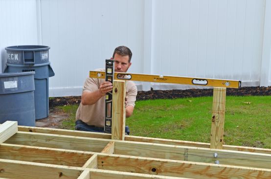
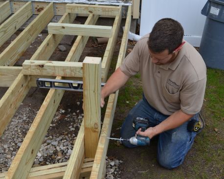
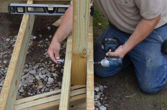
The initial deck framing was fairly conventional. After leveling our two reference joists, we inserted the beam below. The helical footing bracket adjusts easily on its screw, so setting the beam height was simple. Once the beam was set, we flushed the top of each joist even with our carefully leveled house ledger, shot nails to temporarily fasten the joist, then installed joist hangers.
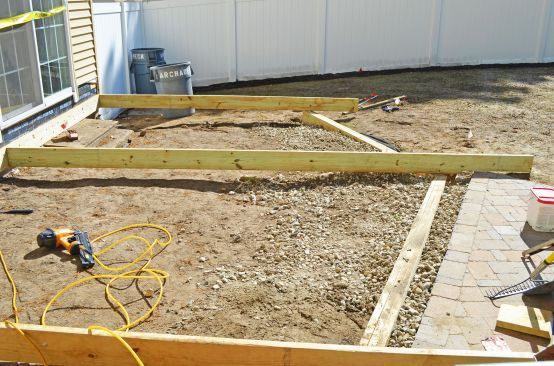
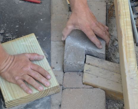
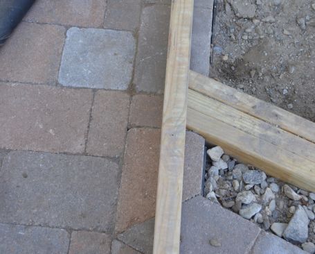
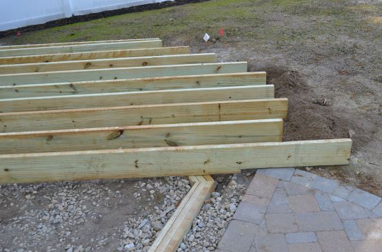
An interesting issue arose on the left side of the deck. Our design called for the deck to extend a few inches over the patio to hide its edge and provide a clean look. We could not let the side joist merely rest on the patio, because the patio is not a structure and is subject to frost. We had to support that side joist like all the other joists. Thus we had to extend our beam into the patio.
The solution was obvious, but somewhat tedious: We carefully notched the patio stones and reset them around the beam. It’s too bad the finished deck hides this craftsmanship.
The ‘Roberts Ridge’
One minor deck problem has irked us for years: The finished surface of our decks was always a little uneven, and our synthetic decking often squeaked under foot. We use #1 treated lumber for our joists, but even these are often slightly warped and vary in height considerably, at times causing adjacent joists to differ in height as much as 1/2 inch or more.
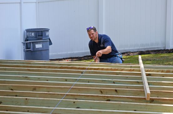
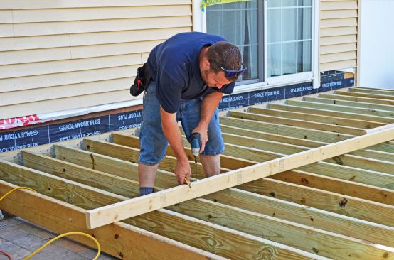
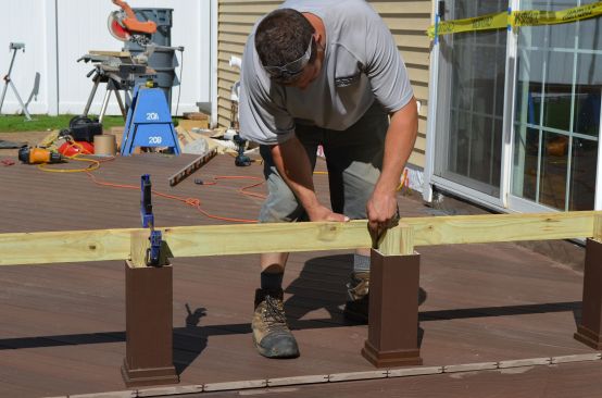
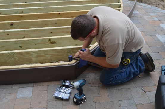
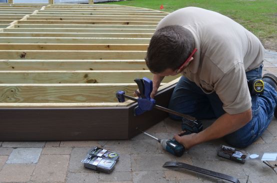
Our carpenter, Eric Roberts, devised a simple, elegant solution. Setting the joists perfectly level at the house is easy, and the beam makes them fairly even near the front edge. The problem lies in the middle. Before installing the mid-span blocking, he laid a straight 2×4 on edge, across the deck and perpendicular to the joists, as a sort of a strongback. He then twisted 6-inch TimberLok or HeadLok screws through the 2×4 “ridge” into each joist below. The screws pulled all the joists into a common alignment, flush to the bottom of our straight 2×4. In 20 minutes, our deck joists were perfectly level and in plane.
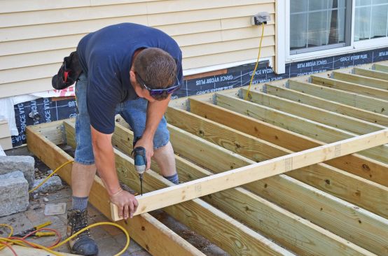
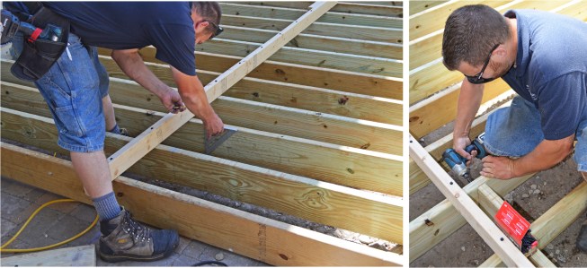
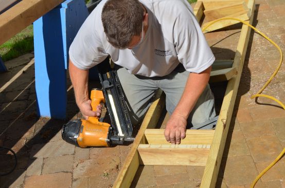
To preserve that consistent, level height, we nailed mid-span blocking in place and secured each piece tightly with 4-inch TimberLok screws, two at each end.
We removed our “Roberts Ridge” when we were ready to begin decking. A little movement and some squeak were noticeable in the frame, but installing the decking (especially because we installed it diagonally) eliminated that. So we were able to level the deck, reduce deflection, and virtually eliminate noise—all in a few minutes, and just with a temporary 2×4 and a handful of screws.
Cutting the Curve
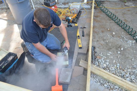
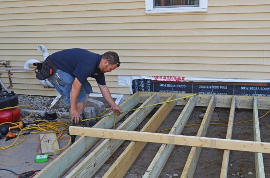
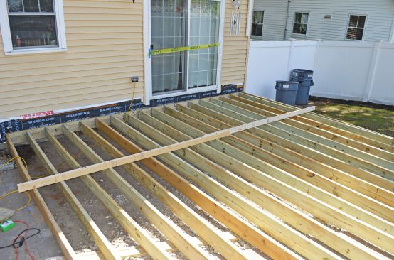
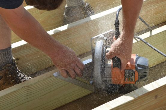
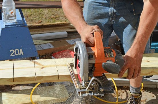
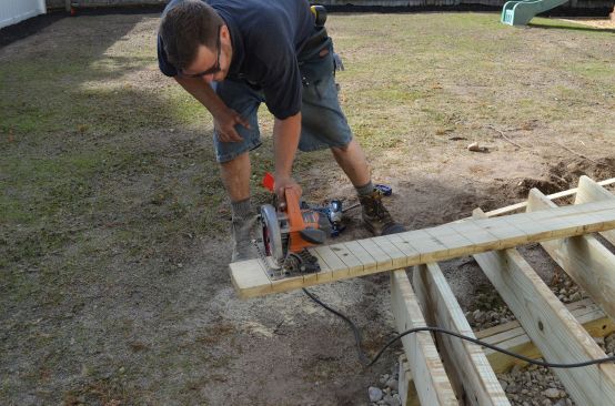
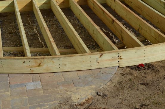
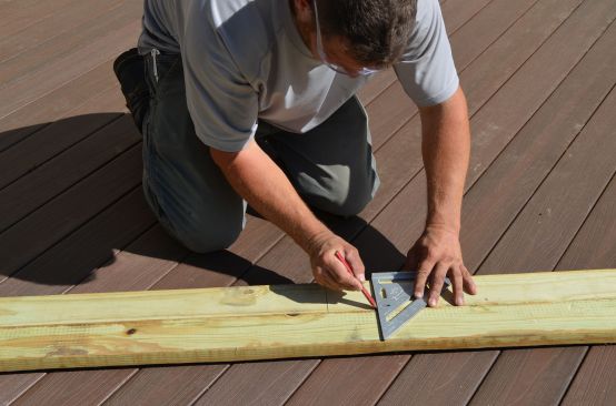
Since we had separated the beam structure from the edge of the deck, building a smooth, evenly curved rim became easy. We marked the curve on the joists using a string-and-pencil compass and cut the joists to length, finishing each cut near the ground with a recip saw.
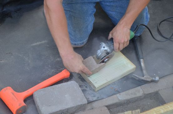
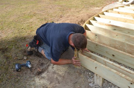
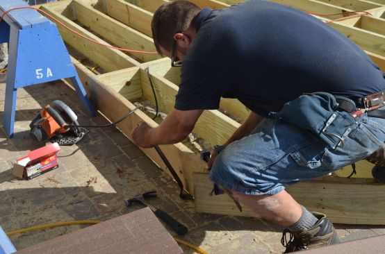
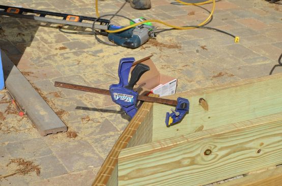
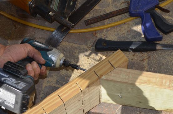
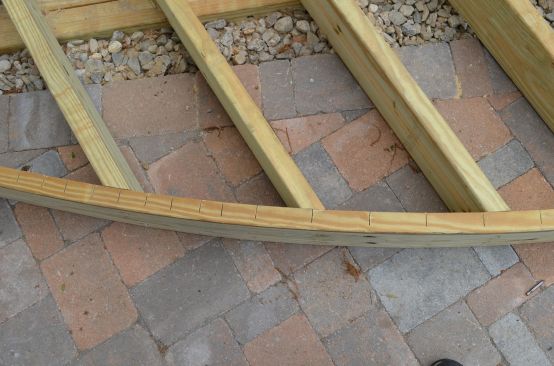
Carefully selecting and scoring the rim joist was crucial to creating an evenly curved deck. The rim joist could have no large knots, and a smooth curve demanded evenly spaced relief cuts. But the long radius (11 feet 6 inches) allowed our rim joist to easily bend into shape. Clamps on the ends and two screws in the middle held the curved rim in place. Leaving the joists loose over the beam allowed us to adjust any joist left or right until it tightly contacted the rim. We then aligned the height and nailed the rim to each joist.
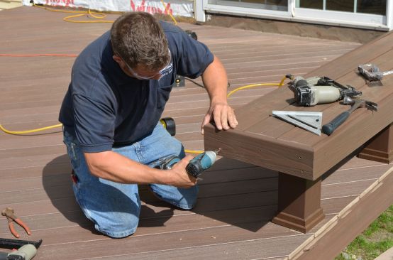
The Safety Bench
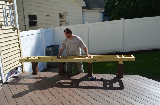
As planned, the step down from the deck to the patio was about 8 1/2 inches, but sloping ground on the right side increased that drop to almost 16 inches—too tall to comfortably or safely step off. We addressed this hazard by building a bench along the edge of the deck.
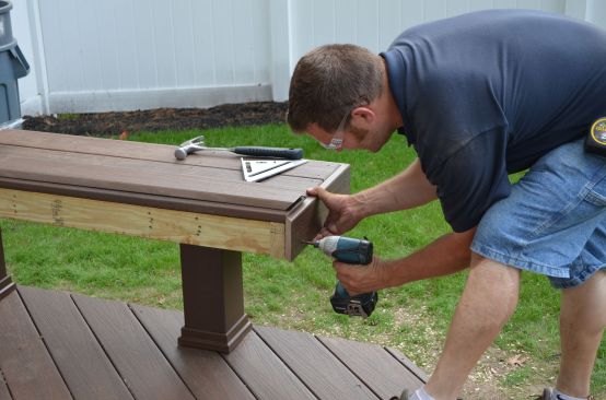
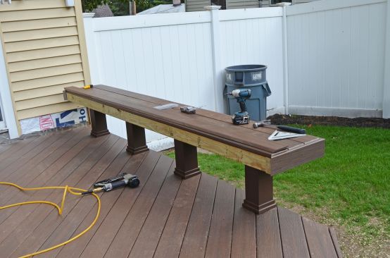
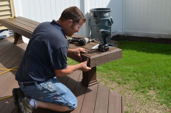
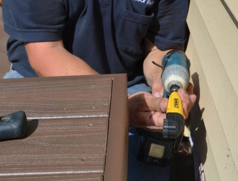
A standard bench with pairs of legs might have looked too massive for this small deck. We opted instead for a “floating bench,” which employs single 4×4 legs that extend down into the deck frame. The key to making the bench solid and stable is to through-bolt each leg between two joists below and between pairs of cross supports on the upper frame. We clad the bench frame with Fiberon’s synthetic ProTect fascia, ripped to height, and softened the bench edges to improve sitting comfort by holding that trim 1/4 inch below the seat.
Treated wood shrinks considerably as it dries during the first months of its exposure, and the initially tight joints in our bench may become loose and wobbly in six or nine months. Fortunately, this shrinkage stops and the wood remains moderately stable thereafter. So we’ll return within a year and tighten our connections.
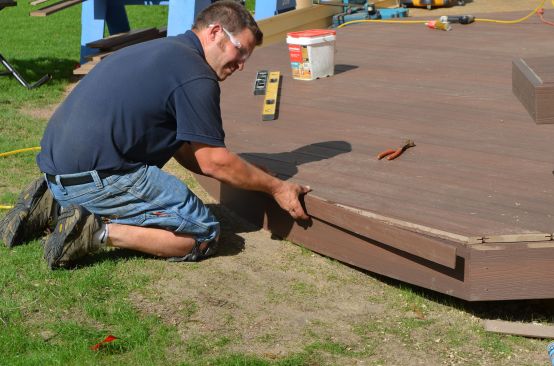
Trimming the Deck
To hide the framing, we covered the rim and side joists with more Fiberon trim material. At 3/4 inch, it was thin enough to easily follow our curved rim joist.
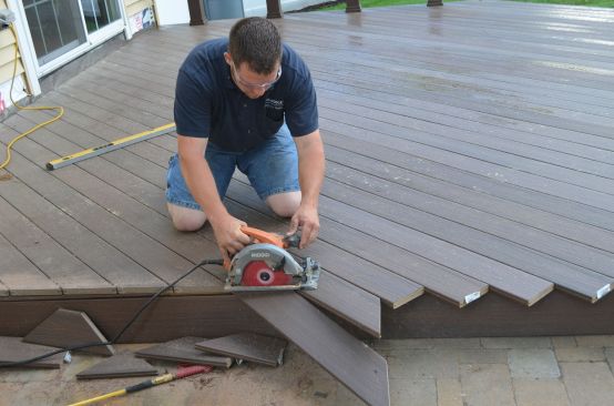
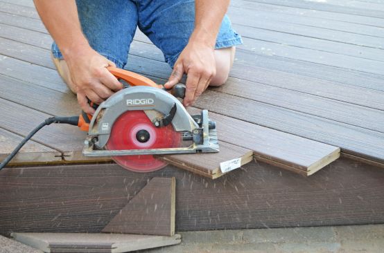
For decking, we used grooved Fiberon ProTect Advantage 5/4×6, fastened with hidden clips. We ran the deck boards diagonally and left them long, hanging past the trimmed rim. Cutting the decking straight along the side trim was easy using a circular saw.
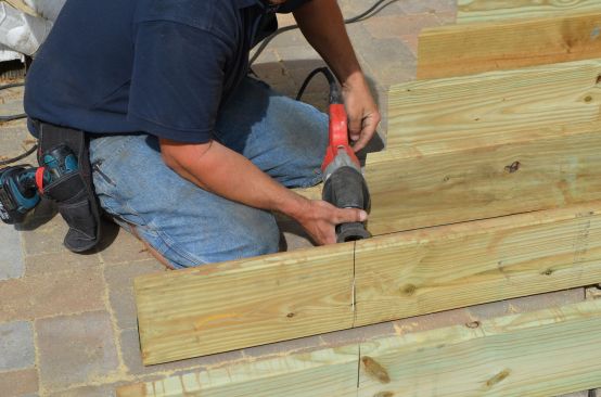
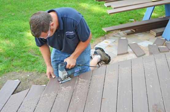
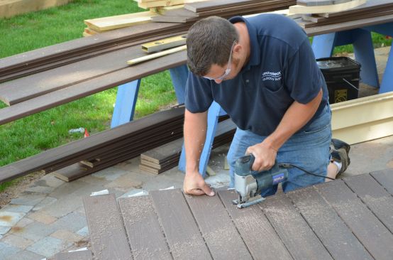
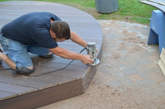
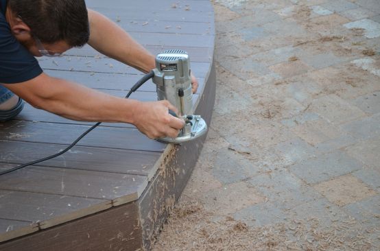
Cutting the decking around the curve took two steps. We first used a jigsaw to roughly cut each board about 1/4 inch beyond the trim. We finished the curve with a router and a 1/2-inch-diameter flush trim bit. The bit’s bearing ran smoothly along the curved deck trim and guided the blades to create a flush, even edge.
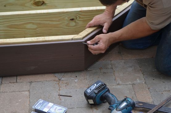
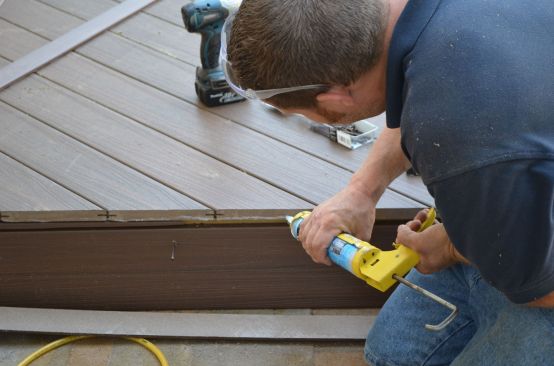
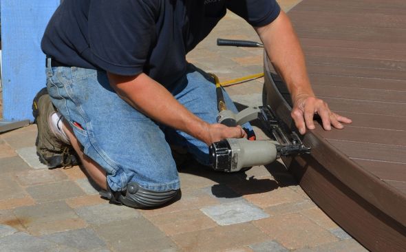
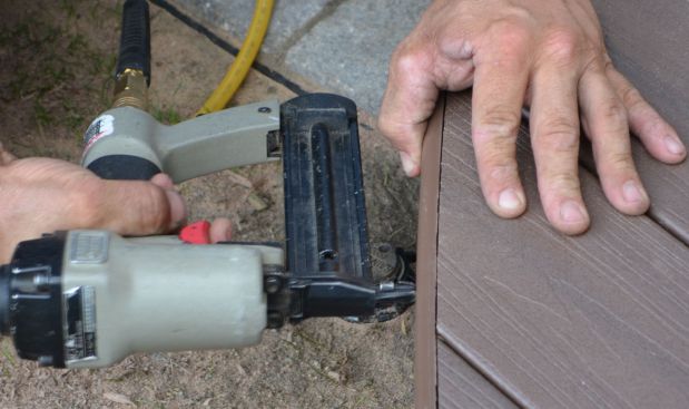
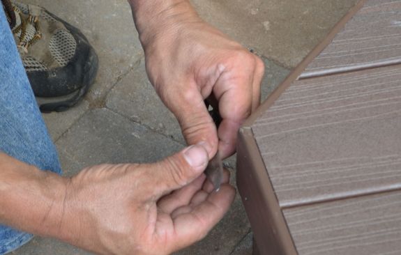
To hide the exposed ends of the decking, we installed a second trim piece, flush with the top of the decking. We ripped the same fascia material to 2 1/2 inches and fastened it with stainless steel trim nails through the lower trim, and with clear silicone and stainless steel pin nails into the ends of the decking above.
The diagonal decking left one small sliver that demanded some care (and an extra face screw), but the results were worth that effort.
Our completed deck looks simple. But making it solid, flat, and quiet, and ensuring that its curve was smooth and even, took some craftsmanship.


