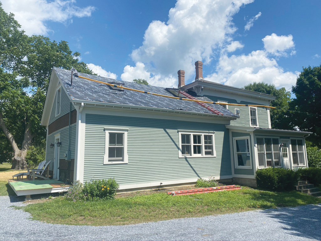
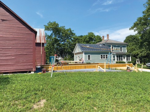
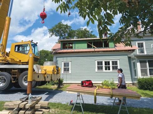
Recently, we added a new master bedroom and bath to the upper level of the west wing of a vintage 150-year-old Vermont home, which had just been purchased by our clients. While the 22′-9″ x 30′ ell’s foundation and first-floor framing were in fine condition, thanks to an extensive kitchen renovation project in 2009 (see “Replacing a Stone Foundation,” Mar/09), our clients had been instructed by their insurance agent to fix its slate roof when they had closed on the house. They also wanted to add shed dormers and move the knee walls out, thus increasing the footprint on the second floor and creating wall space for new windows for the master bedroom suite. All of the work would have to take place without disrupting the kitchen below.
Prepping the roof. The roof had been severely compromised due to the weight of slate sitting on roof framing that had been designed for cedar shakes. The slate had been installed directly over cedar shakes, in fact, so we started by removing both layers. Then we covered the roof sheathing with synthetic roofing underlayment to keep the space dry until we were ready to cut in the new shed dormers.
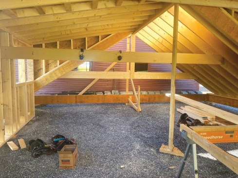
On the interior, we removed drywall and the dense-packed cellulose that had been used to insulate the walls and ceiling. This revealed hand-hewn 5×7 timber rafters, which had been reinforced at some point with sistered 2x12s. The rafters were pegged at the peak and nailed to the wall top plate on a roughly 3-foot-on-center layout. In order to cut in our clients’ proposed 21-foot-wide dormer on the south-facing side of the roof and 12-foot-wide dormer on the opposite, north-facing side, we would need to install a structural ridge to prevent the walls from bowing out even more than they already were.
On the interior, workers vacuumed up the old cellulose insulation, then reinforced the existing 2×12 framing that had been sistered to the old timber rafters during a previous renovation with rafter ties so that the roof could safely be lifted with a crane.
With no interior walls available to post up midspan support for a structural ridge, it would be next to impossible to “cut” the large dormer on the south side and the shorter dormer on the north side into the roof without exposing the structure to weather. Leaving the sheathing intact and installing a dropped ridge underneath the rafters wasn’t an option either, because it would sacrifice much-needed headroom. And even if we could figure out these details without risking water damage to the kitchen below, we would still be left with the challenge of flattening, straightening, and resheathing what was left of the main pitch roof to accept standing seam roofing.
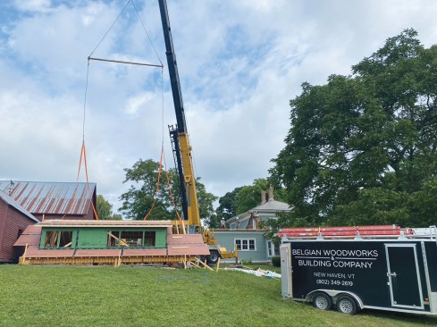
After sharing these discoveries with the client, I proposed the safest bet was to rebuild the entire roof system on the ground, then use a crane to remove the old roof and set the new one in place. Catamount Crane Co., run by Cole Goyette, a good friend of mine, would be my go-to for “the big move.”
Framing the new roof on the ground. I started by mapping the overall size of the exterior walls and shot the elevations of the existing top plates with a laser. Each eaves wall had roughly a 1 1/2‑inch bow, caused by the weight of the slate, with the plates dropping around 3 inches from east to west (away from the house) along their 30-foot span. With only 2 feet of balloon-framed stem wall extending above floor height, we knew we couldn’t do anything to fix the bow in the walls without disturbing the ceiling and kitchen below. The elevations, however, needed to be trued back up in order for the new roof to sit level.
With the bowed walls and the odd size of the old, rough-sawn lumber framing, it was difficult to determine if the structure was square, and—if not—just how far out-of-square it was. My solution was to use a laser to plumb down from the “peak” of the rafters to the old subfloor at either end of the building and use those marks to snap a centerline representing the center of what would become the ridge. Verifying that back to the corners that mated up to the main house, we were within 1/4 inch of square over 20 feet. That was within the tolerances needed to build our new structure truly square and make adjustments later.
Next, we built a 22′-9″ x 30′ frame out of LVLs in the parking area to represent the structure’s footprint, propping it up so that it was level. After squaring it up, we checked all four sides with a string line to make sure they were straight. Then we plated the two eaves walls of the LVL frame with 2x6s, which would eventually become the upper plate of the double top plate that we would install to cap the balloon-framed walls.
The new roof would be built on the ground and lifted into place with a crane. To provide a “foundation” for it, the author and his crew carefully measured the structure, then set up a braced and leveled LVL frame on the ground representing the tops of the structure’s walls.
On the existing roof, the old rafters terminated at the very outer edge of the single top plate, with the soffit and roof overhang simply applied from outside. Initially, I thought that the soffit, fascia, and roof crown were still worth saving, if possible. However, I also wanted the eaves to be structurally sound, with the new rafters overhanging the wall plates and birdsmouth seat cuts in the rafters.
The position of the ridge was dictated by where it mated up to the main house, while the new roof framing was restricted by the needed clearance for the height of an interior door, which could not change. We didn’t want to disturb the siding on the main house, and we wanted to keep the already-sided gable wall on the addition largely intact. That meant that the ridge height and roof pitch of the old and new roofs had to match exactly.
We ended up with a 7.5/12 pitch, with a 6 1/2-inch HAP cut in the birdsmouth. Because we planned on double top plates, we had to remove 9 1/2 inches from the top of the existing walls in a level plane for the new roof structure to mate up to the old building.
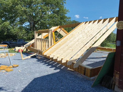
Workers tacked 2×6 plates to the LVLs, then installed a double 1 3/4-inch-by-14-inch LVL structural ridge. The new roof was framed with 2×12 rafters.
The walls of the south-facing (shown above) and shorter north-facing dormers were framed with 2x6s. The structural ridge on the east side of the roof was sized to be inserted into a pocket framed in the existing wall.
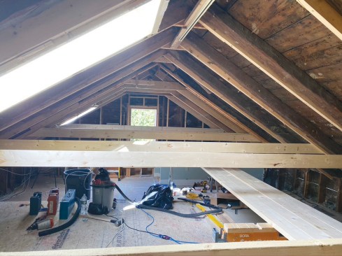
For the structural ridge, we specified double 1 3/4-inch-by-14-inch LVLs, with 2×12 rafters and roughly 7-foot-long collar ties to form the ceiling. We dropped the ceiling in the lower level to make room for a recessed cassette heat-pump head. The dormer walls were framed with 2x6s, with LVL headers in the window openings.
We sheathed the walls with 7/16-inch Zip System sheathing and used 5/8-inch Zip T&G panels to sheathe the roof. At the peak, we cut the final course of sheathing to size and Zip-taped the joints, but we fastened the panels to the framing with only a few screws in each panel. That allowed us to remove the screws and fold the panels back so that we could rig crane straps to the ridge.
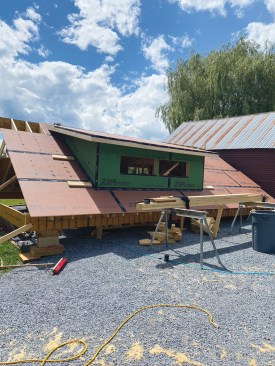
At the ridge, the 5/8-inch T&G Zip panels used to sheathe the roof were cut to fit, tacked in place, and Zip-taped so that they could be folded back during the lift.
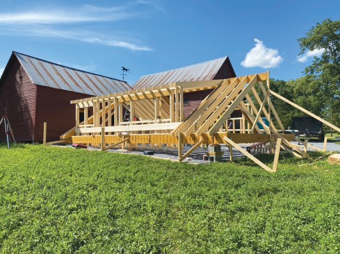
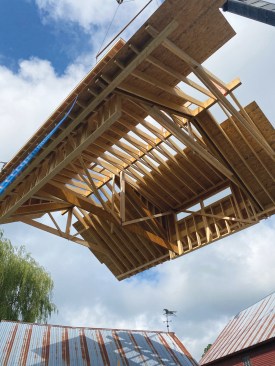
We had decided—with Cole’s (the crane operator) input—that the roof system could be picked up from four points along the ridge. Since neither end of the structure would have a gable wall for support, we framed a series of 16-foot-long temporary strongback T-shaped 2×6 rafter ties, screwing them to the rafter pairs at the gable ends and to the rafter pairs flanking the short shed dormer. To reinforce the assemblies, we posted each rafter tie up to the ridge and installed pairs of diagonals. Finally, to help resist the force of the walls and eaves wanting to fold inward during hoisting, we installed a full-width LVL fastened on each side to doubled window king studs, plating the LVL with 2x6s.
Temporary T-shaped rafter ties were added to the framing to reinforce the roof system during the lift.
Lifting day. To reinforce the old roof system, we had fastened rafter ties to roughly every other rafter pair with structural screws. These reinforced rafters become our lifting points, as the wooden pegs at the peaks offered minimal shear strength. With Cole’s 70-ton crane on site, we divided the roof into three sections, cutting down the rafter bays from the peak all the way through the top plate with a reciprocating saw. Knowing that we would eventually have to remove 9 1/2 inches of studs below the top plate, we also cut horizontally through the studs at the upper board sheathing break.
On the day of the lift, workers cut the old roof into three sections, which they had reinforced with truss-like framing. Prior to removing each section, they cut through the studs and sheathing just below the top plate.
Next, we cut a small opening in the peak at the center of each section for the lifting strap to go through. Before lifting away each section, we installed a triple 2×6 beam underneath the section’s supporting rafter ties. We also posted up from either end of the beam to the peak with 2x6s, effectively creating a pair of trusses that would support each roof section. Then we hooked the lifting strap to the beam and hoisted the roof away, section by section, relying on the small “windows” in the sheathing to guide the straps and keep the roof sections from rolling over.
The lifting straps were threaded through small openings cut into the roof sheathing at the ridge.
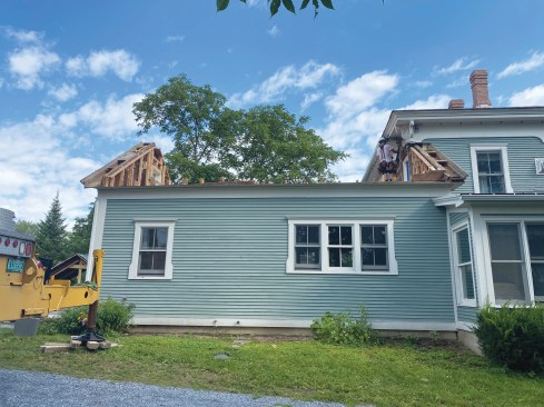
With the roof removed and the balloon-framed gable end walls exposed, the structure was ready for its new roof.
With the roof out of the way and the wall framing exposed, we shot a laser line around the building and snapped out the new height needed for the existing studs to set the new roof system level. Then we cut the studs to the line with a 10 1/4-inch circular saw, creating our new level plane. Finally, we snapped a line on the board sheathing that was slightly below the height of the studs and cut to the line with a reciprocating saw. When making the seat cuts on the new roof rafters, we had cut secondary notches 3 inches below the seat cut to accommodate the sheathing.
The west-facing gable wall was now free-standing, but because it was balloon-framed, we felt comfortable leaving it loose for the time being while we nailed off the lower of the two top plates to the tops of the studs in preparation for the new roof.
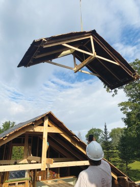
Flying in the new roof. While the crew and I reinforced the new roof structure for hoisting, Cole unscrewed and folded back the finish course of Zip sheathing to expose the ridge and begin rigging his lifting straps. He hung a spreader bar off the crane’s main hook with two 20‑foot steel cables, then choked 40-foot-long straps to the ridge. The longer the strap (and therefore the shallower the angle between the lifting points on the ridge and the hooks on the steel cables), the less likely the straps would slide inward towards each other under the weight.
Hung from a spreader bar, lifting straps were choked to the ridge at the four locations that had been reinforced with the temporary T-shaped rafter ties.
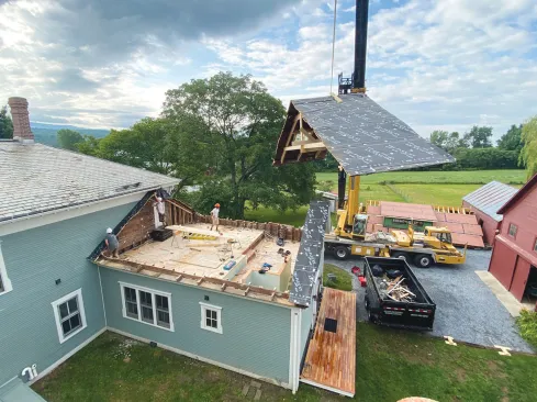
Because we had two different-sized dormers, the weight of the roof wasn’t evenly distributed from side to side. So a test pick was performed, during which we used another strap hooked to the long dormer and a come-along to balance out the heavy side. At the same time, we adjusted the lifting straps so that the east side—the side mating up to the existing house—would be slightly lower than the west side, providing the geometry needed to tuck the ridge under the eaves of the main house while clearing the free-standing gable wall at the other end.
During the lift, a worker coordinating with the crane operator used a tag line to help position the suspended roof.
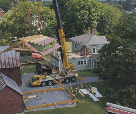
Because of the unequally-sized dormers, the structure was unbalanced, and a strap fastened to the large dormer and tensioned with a come-along was needed to keep it level.
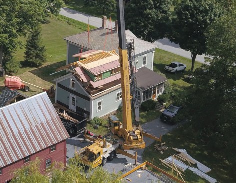
Tucking the new roof’s structural ridge under the main house eaves while fitting it into a beam pocket in the existing framing and slipping the assembly into place on top of the gable end wall was tricky.
At the end of a long day, the new roof was in place and the structure was buttoned up against the weather.
On the east side, we had framed the LVL ridge 4 inches long to allow us to post up to the ridge inside the interior wall of the main house. Unfortunately, the extended ridge became a bit of a headache, as we didn’t have enough clearance between the east strap near the end of the LVL and the eaves above to join up to the main house without the strap hitting the eaves. Because the east side was lower, we were able to set it down temporarily, taking just enough weight off the strap to be able to slide it over to the other side of the rafter bay that it was rigged to. Then we picked the structure back up and slid it over into its final position on top of the new plates. Once we nailed the plates together, we unhooked the straps, cut the sheathing to length against the main house, folded the roof sheathing back into place, nailed everything off, and taped all the joints with Zip tape. It was a long day, but now we were watertight.
To match the new roof trim to the out-of-level ell, workers had to remove the existing soffit and fascia.
Then they installed a secondary frieze board molding detail, complete with new fascia, soffits, and crown molding.
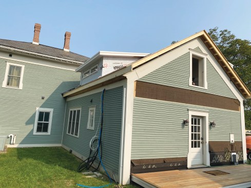
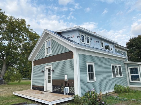
Stitching the pieces back together. Due to the ell’s out-of-level condition, we had to remove the existing soffit and fascia. To match the new trim with the old and hide the problem, we installed a secondary frieze board molding detail, complete with new fascia, soffits, and crown molding, finished off with a new standing seam metal roof.
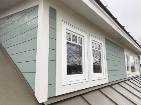
The dormers were clad with gapped shiplap siding, and a new standing seam metal roof was installed.
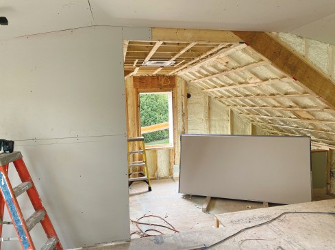
On the interior, new partitions were framed for closets and a master bathroom, and the wall cavities and rafter bays were sprayed with closed cell foam insulation.
On the interior, after framing new interior partitions for closets and a master bath, we roughed-in new plumbing and electrical. Then we air-sealed and insulated the space with spray foam and got to work on the finishing details.
Photos by Alan and David Schmidt.