Dealing with some of the typical challenges that crop up on hill…
I’ve been a remodeler in Marin County, Calif., for about 30 years and have done many makeovers of vintage hillside houses. In that time, I’ve also remodeled four of my own homes, and in each case, the investment paid off when I sold and moved.
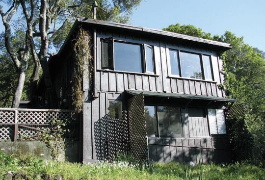
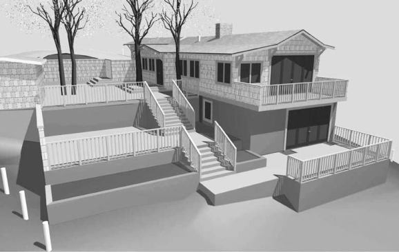
This past year I had the chance to do it all again. I’d recently sold my last house and was ready to invest in a new one. By good fortune, the right property presented itself: A rustic home originally built as a hunting camp, with beautiful valley views, in a nice part of a desirable bedroom community outside San Francisco. The timing was right for my business, too. Work has been slow in California; investing in this new property was a way to keep my crew busy for a few months and to keep us in practice.
In this article, I’ll show how we handled some of the typical challenges that crop up on hillside remodels. I’ll concentrate on demolition, excavation, and the foundation. Once the foundation is level, square, and stable, everything else falls into place more easily.
An Opportunity, With Limits
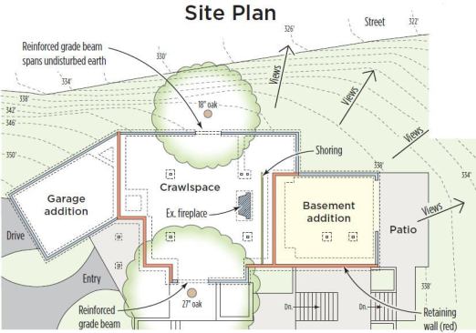
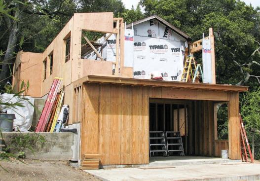
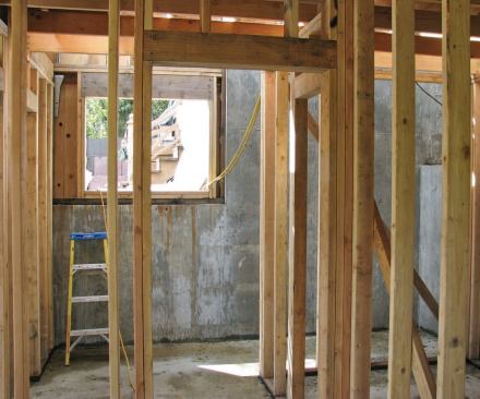
Although the site has excellent easterly and southerly exposure, with a lovely view of a nearby ridge line, the structure needed some attention. For it to work as a modern dwelling, the entire floor plan would need to be radically revised, with new window and door openings to take advantage of the setting. The house also needed more floor space, a problem on the tight, steeply sloped lot. Rather than spread out on the site to add living space, we would have to undercut the existing house and build back into the hillside underneath it. The plan was to excavate and build new basement walls, some of which would also have to act as retaining walls to resist soil pressures independently of any bracing from the floor system. That’s because a stairwell opening cut across the plan on the uphill side of the house and the floor joists ran parallel to the wall, so they couldn’t be used for bracing.
We would also have to replace the existing foundation with a new one that could meet current California seismic codes. As an added challenge, while building all these new footings and foundation walls, we were required to preserve as many of the existing “heritage” trees on the site as possible, including some that had roots growing underneath the existing house. Luckily, the site did have one big advantage — excellent soil with good bearing strength and drainability.
Cribbing and Excavation
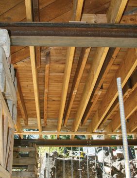
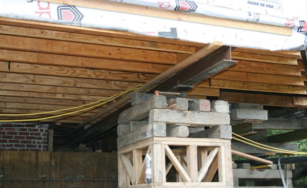
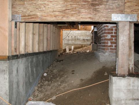
The existing floor was underframed and a little peculiar, with diagonal girders interrupting undersized floor joists at mid-span. So as the first stage of the job, we removed the girders and supplemented the sawn floor joists with the full-span LVLs our structural engineer had specified for the new floor system. This gave the house-moving company we hired to crib the structure, Wacker and Sons of Penngrove, Calif., a solid, stable platform to support. Before the house-movers started, we had to dig out holes for the cribbing under the building by hand, first verifying all final footing elevations for the new foundation. We wanted to be sure that the cribbing was set at least as deep as our new footings; otherwise, we might risk undermining the temporary supports during excavation.
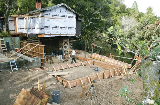
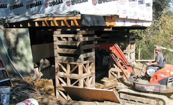
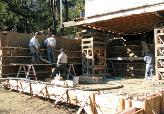
Once the cribbing was set and the house supported on steel I-beams, we tore out the existing lower-story walls and started digging into the hill behind the house. In addition to hand-digging, we were able to put two mini-excavators to work at the same time — one digging out the bank under the building and the other transferring the dirt to a dump truck parked on the road.
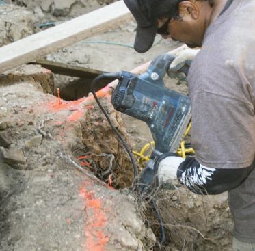
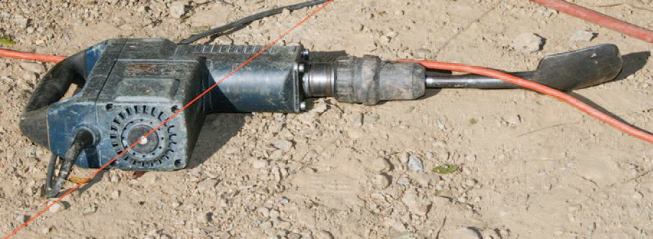
Within a few days, the bulk of the excavation was complete and the soil removed. We then turned to digging the footing trenches. The mini-excavators were able to cut most of them, but in a few tight spots we had to dig by hand. The rocky soil was a bit of a challenge, so in some places the crew had to use a rotary hammer equipped with a shovel bit. The advantage of the hard soil is that the trench walls held their shape well, so we didn’t have to use forms for the footings.
Shoring for Safety
The plans called for extensive digging under the house. To avoid…
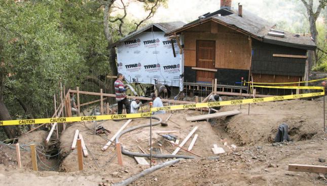
The simple stem walls for the house perimeter would be poured in one shot — footing and stem wall at the same time. But the big retaining walls that formed two sides of the new basement living space would be poured in two steps — first the footings, then the main walls.
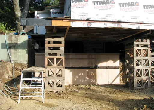
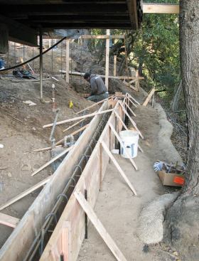
Before we put our crew under the house to place the rebar and set the forms for those tall walls, however, we wanted to be sure the uphill bank was stable. For one thing, we didn’t want to lose any of the structures that rested on the remaining soil underneath the house — particularly the existing fireplace and chimney, which sat on a pad on grade from decades ago. But more important, we had to be sure that it was safe to work under there — not just when we were forming the walls, but later, when we would have to get in between the new retaining wall and the bank. Once that wall was in place, workers would have to work behind it to strip forms, apply waterproofing, and install foundation drains.
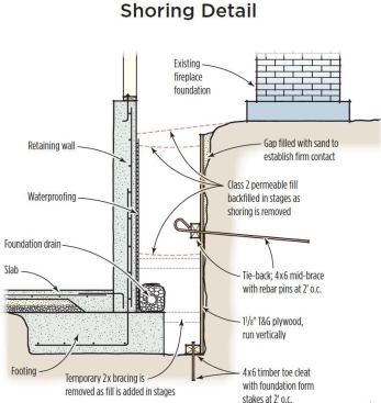
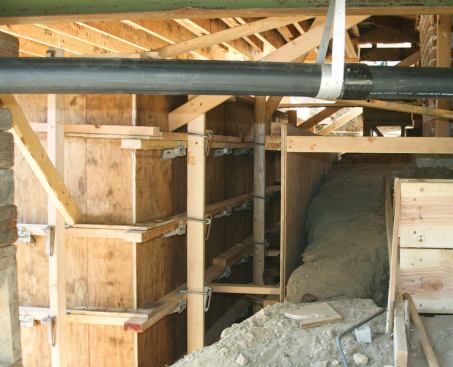
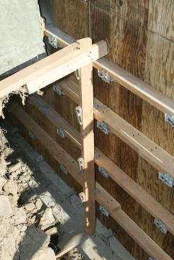
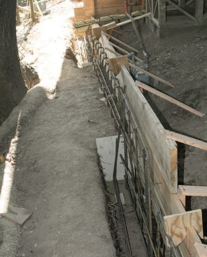
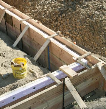
So even though the soils were firm, we decided to shore the bank cut just in case. We started by anchoring a 4×6 cleat to the soil at the base of the cut, using foundation form stakes at 2 feet on-center. Then behind that, we set sheets of 1 1/8-inch plywood, run vertically. We used tongue-and-groove plywood, so the pieces fit together into a sort of panel system. Then, about 6 feet up the panels, we attached another 4×6 timber across those five sheets of plywood as a mid-brace.
We drilled through the 4×6 cleat to make pilot holes for our soil pins, then drilled lengths of 5/8-inch rebar into the bank at an angle. As we got to the point of refusal, we cut the rebar off, leaving about a foot sticking out, which we bent back toward the plywood in a loop. This gave us a soil-reinforcing tie-back that held the plywood in place. Finally, we filled the gap between the shoring and the bank with sand, to establish firm contact.
It was worth the effort. Once the retaining wall was formed and poured, we were confident the narrow space was safe to work in. After waterproofing the back of the wall, we figured out how to remove the shoring system and place backfill at the same time: First we positioned short pieces of 2×4 between the plywood shoring and the new retaining wall, to temporarily brace the shoring. Then we pulled up the 4×6 cleat at the toe of the shoring and began to backfill between the shoring and the retaining wall with Class 2 permeable fill (a standard mix of drainable sand and gravel defined by the California DOT), removing our temporary braces as we went. We then cut off the ends of our rebar pins so we could pull out the strongback, added some more fill, and yanked out the plywood shoring using a come-along. Finally we topped the whole space up with Class 2 permeable, leaving a tight pack between the retaining wall and the bank cut.
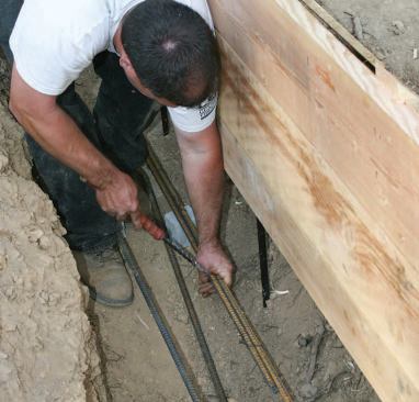
Working With Rebar
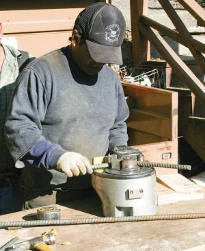
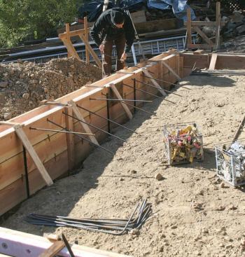
Because of the seismic engineering requirements in our region, and because we often work on hillsides, our concrete reinforcement usually goes far beyond the minimal steel required on a flat site outside of earthquake country. The size and quantity of the rebar are specified by our structural engineer, who also calls out the length of overlaps at splices and the depth of concrete cover. Typically, we make continuous bends around footing corners, and we also bend continuous pieces of steel at the junctions between footings and walls and at steps in the footing elevations. That means we’re used to bending steel. We own a Hitachi rebar bender that can handle #4 and #5 bar, but on this job we needed to bend some #6 bar, so we rented a heavier bender.
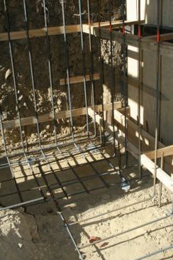
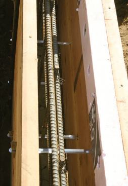
Some of the foundation walls on this job also serve as retaining walls, which means they have to hold back soil pressure as well as support the structure. For this house, we used a typical retaining wall design. We start by placing and tying a mat of reinforcing steel in the wide footings. Some of the bars bend and come up vertically out of the footing, all the way to the top of the retaining wall. We pour the footings first, at the thickness specified in the engineer’s drawings, then tie the horizontal steel in the wall, again according to the engineer’s spec.
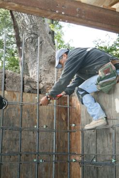
These retaining walls needed a grid of horizontal and vertical bar spaced as close as 12 inches on-center — and, for that matter, so did our patio slab. That’s a lot of tying. We don’t have a power rebar-tying tool, so our crew uses a manual tool that works like a Yankee screwdriver: After you grab the two ends of the wire, you pull the sliding shaft and it quickly makes the twist. It’s much faster than hand-tying with pliers and cuts down on wrist strain.
Formwork
Where the roots of old oak trees grew under the house, the crew …
For forming stem walls, we use stacked 2x10s supported on form stakes; flat metal snap ties that also support the horizontal rebar in the wall prevent the forms from spreading during the pour. For taller walls we use a forming system made by Meadow Burke (meadowburke.com), which is designed to work with plywood and 2×4 walers and strongbacks. The hardware lasts for years, and we can reuse the plywood and 2x4s on many jobs before it wears out.
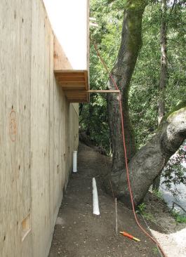
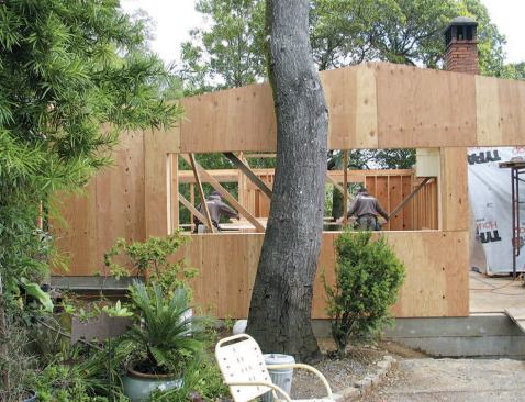
Stepping over tree roots. As I mentioned earlier, one of the tricky requirements on this site was the need to preserve existing trees. Certainly for me as a homeowner, a big part of the property’s beauty is the old oak trees. The town was also concerned about preserving them. So where the root systems had grown underneath the house, we worked with our engineer to create footings that would meet seismic codes without cutting through the roots. Where the foundation intersected the roots of an important tree, we stopped trenching, leaving the roots in undisturbed soil. At that point, we formed a footing dam, then formed a reinforced grade beam that overlapped the stem wall by a foot or two at each end and spanned the undisturbed earth.
Tying footings to slabs. There was one other place where we had to do some interesting formwork: the joint between the patio slab and the stem walls it rests on. Here, we used our usual 2×10 form boards for the stem wall, but attached a strip of polystyrene foam to the inside of the boards at the top to create a shelf for the slab to sit on. We drilled holes through the foam and form boards so that we could place rebar elbows that projected out into the area where the slab would be. After placing concrete and stripping the forms, we tied the grid of rebar in the slab to the rebar projecting from the perimeter stem wall.
Over the years, I’ve seen the rules for slab reinforcement get tougher and tougher. When I first started, we used welded wire fabric. After that, we went to #3 rebar 18 inches on-center, in both directions. Next the spacing decreased to every 12 inches on-center, and now we use a grid of #4 bar 12 inches each way. It’s a lot of steel, even in our part of the country.
Good Neighbor
In general, I found it well worthwhile to be proactive about the environmental and neighborhood issues on this site. We added space under the house to minimize additional footprint, we were conscientious about preventing erosion and silty runoff, and we went to considerable lengths to engineer a solution that would preserve the mature trees on the site. All these things were appreciated by local officials and helped us keep a good relationship with the town.
Jeff Kerr owns and manages Kerr Construction in San Rafael, Calif.


