Forces in a Retaining Wall
Soil pressure on a retaining wall increases with the depth of the soil it is holding back. (Forces in a Retaining Wall, below). Walls can fail in bending, by sliding, or by toppling. When engineering a wall, all three failure modes must all be analyzed.
Drainage for Retaining Walls
Soil pressures on a retaining wall increase drastically when the soil is saturated (see Soil Types for more on soil types and pressures). At the same time, the chance of soils sliding or overturning increases when soil is wet. Backfilling with poorly draining material, or failing to provide positive drainage, greatly increases the odds of wall failure. Always backfill retaining walls with free-draining granular material (sand or gravel), and provide drains that allow water to escape from behind walls (see Drainage).
Reinforcing Retaining Walls
Follow general guidelines for reinforcing foundations (see Rebar).
In a retaining wall, which is not braced at the top like a foundation wall, steel goes on the side of the wall close to the soil load, where tensile stresses occur (below).
Poured Concrete and Masonry Retaining Walls
For concrete and masonry retaining walls less than 5-ft.-tall, follow guidelines for steel placement and dimensions as shown below. Taller walls should be designed by a qualified engineer.
Figure: Masonry Retaining Walls
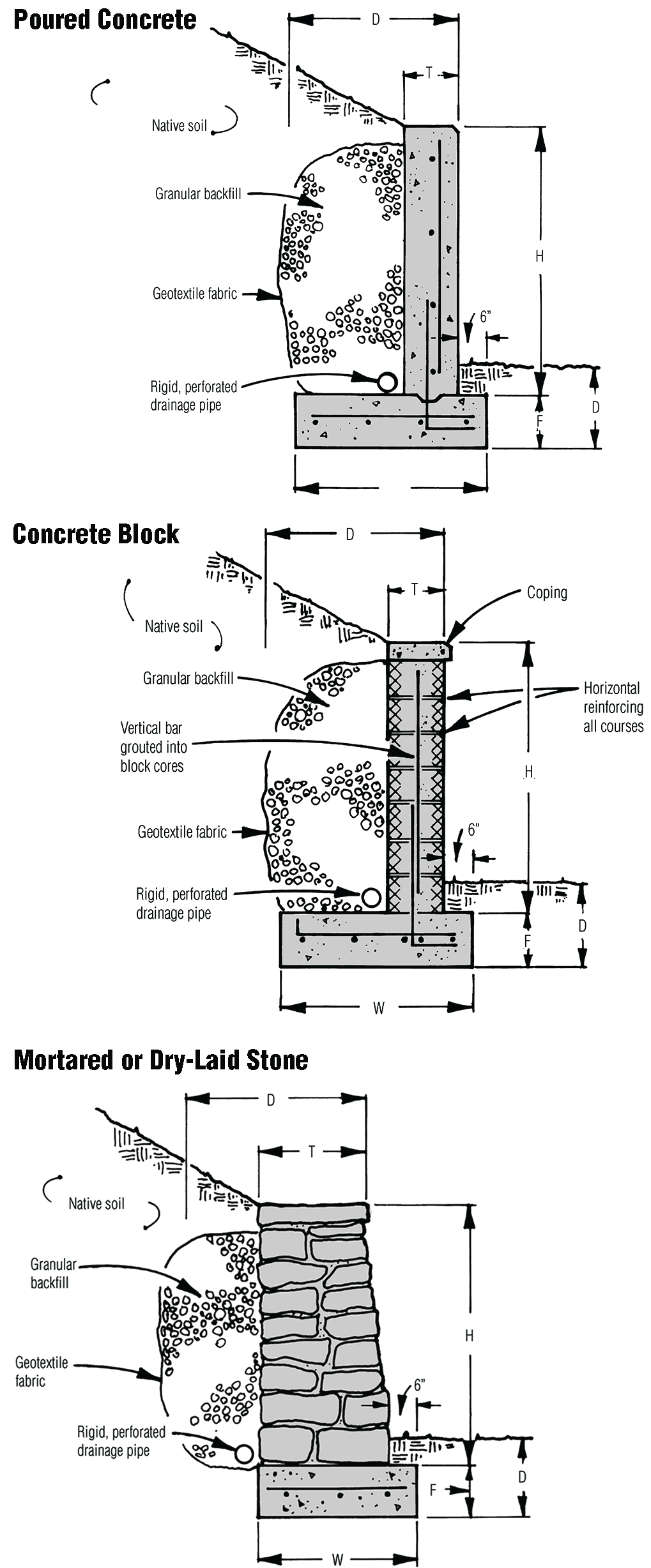
| Recommended Dimensions for Low Masonry Retaining Walls {{fn|Suggested details for walls no higher than 5 ft. where dense, coarse-grain soil exists below footings. Not for loose or soft sand, peat, or clay.}} | ||||||
|---|---|---|---|---|---|---|
| H | W | Steel Rebar | Bar Spacing | F | T | D |
| 2′ | 20″ | #3 (3/8″) | 2′-0″ o.c. | 9″ | 8″ | Local frost depth or 12″ to 18″ |
| 3′ | 25″ | #4 (/2″) | 2′-0″ o.c. | 10″ | 8″ | |
| 4′ | 32″ | #5 (5/8″) | 2′-0″ o.c. | 11″ | 10″ | |
| 5′ | 42″ | #5 (5/8″) | 1′-6″ o.c. | 12″ | 12″ | |
Timber Retaining Walls
Crib walls built out of landscaping ties function like a gravity wall. The mass of earth in the crib structure holds back the pressure of the soil behind it. Wood must be treated against rot. Timbers can be joined with 10- or 11-in.-long, hot-dipped, galvanized spikes or with rebar dowels in pre-drilled holes.
Crib walls can be as high as 30 ft., but a qualified engineer should design walls higher than 5 ft. For walls 5 ft. or shorter, follow the guidelines shown below.
Figure: Timber Retaining Walls
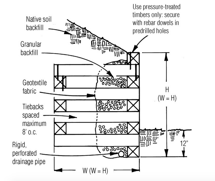
Recommended Dimensions for Low Timber Crib Walls {{fn|Details apply to walls no higher than 5 ft.}}
| Timber Size | Dowel Size | Spacing of Tiebacks |
|---|---|---|
| 6X6 | 1/2″ (#4 bar) {{fn|In acidic soils, increase by 1/4 in. or use hot-dipped galvanized.}} | 6′-0″ (max.) |
| 8X8 | 3/4″ (#6 bar) {{fn|In acidic soils, increase by 1/4 in. or use hot-dipped galvanized.}} | 8′-0″ (max.) |
Tiebacks for Low Walls
For very low timber retaining walls in granular soil, you may be able to use tiebacks instead of an actual crib design (see below). Tiebacks spaced 16 ft. o.c., staggered on alternate courses, are typical. (For greater holding power, space tiebacks closer.) Tiebacks should extend into soil a distance equal to the wall height.
Interlocking Block Retaining Walls
Geogrid is a plastic grid material used to reinforce soil banks. In combination with interlocking block systems, it can be used to create a block-faced earth retaining wall that functions similarly to a concrete gravity retaining wall (Interlocking Block Retaining Walls, below).
Engineered Tall Walls
A qualified engineer should design block walls higher than 5 ft. Usually, the vertical spacing of the geogrid is about twice the depth of the masonry units, and the geogrid extends into the soil horizontally a distance equal to 60% to 80% the total wall height, depending on the surcharge above the wall.


