A Victorian-era house's shallow spreadfooting foundation had set…
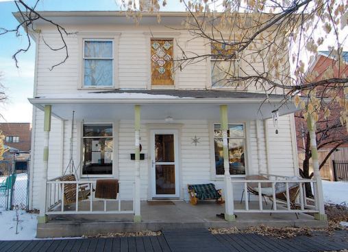
Back at the turn of the 20th century, miners flocked to the new town of Louisville, Colo., to work in its emerging coal industry. There must have been some skilled carpenters among them, because the town is filled with beautiful Victorian-era homes. Unfortunately, they built the foundations the same way they built coal mines, driving wood pilings into the ground and framing right on top of them. Over the years, those old wood foundations have failed and been replaced with a hodgepodge of stone, concrete, and block, none of which is particularly well-suited for the area’s expansive clay soils.
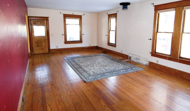
Such was the history of my clients’ house: The shallow spread-footing foundation that replaced the original perimeter pilings had settled over the years, causing the wood floors of the foursquare home to sag, buckle, and splinter.
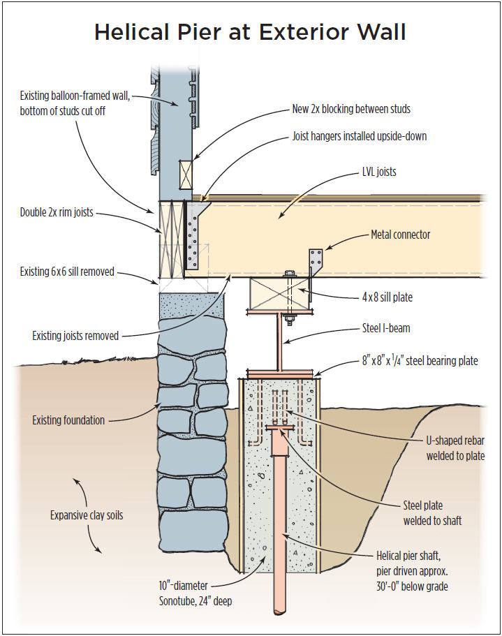
When one of those splinters lodged in their daughter’s foot, my clients decided it was time to contact an engineer, who proposed replacing the entire ground-level floor system with a new one supported by helical piers (see illustration). The piers and new LVL floor framing would also support the wall framing and roof loads; the old concrete foundation would remain in place, but it would no longer serve any structural purpose. I was hired because I was the only builder bidding the job who suggested that this would also be a good time to improve the home’s energy performance by air-sealing and insulating the new framing.
Demolition
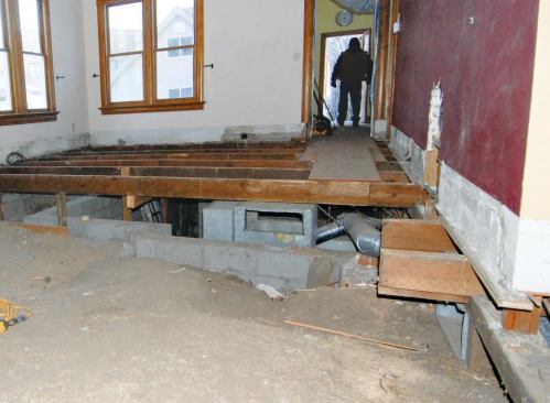
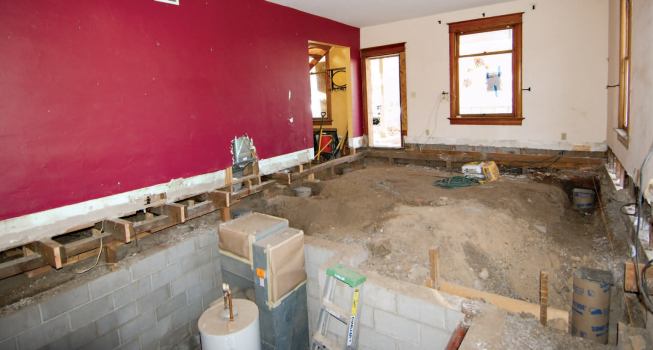
Our goal was to stabilize the foundation and flatten the floor, but not necessarily to level the house, since jacking the walls could damage the home’s old plaster finishes. My clients briefly considered raising the house and adding a full basement, but decided they didn’t need the additional space. A previously built basement-level masonry-block mechanical space would remain.
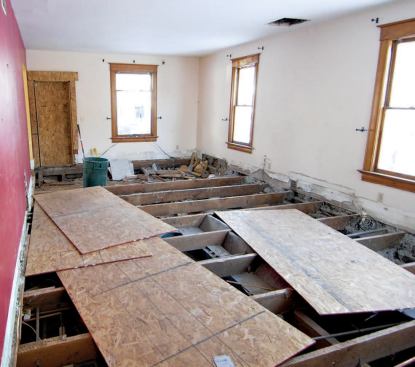
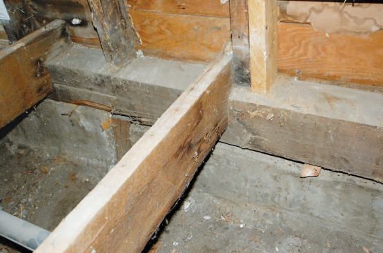
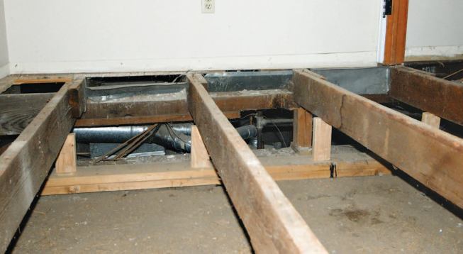
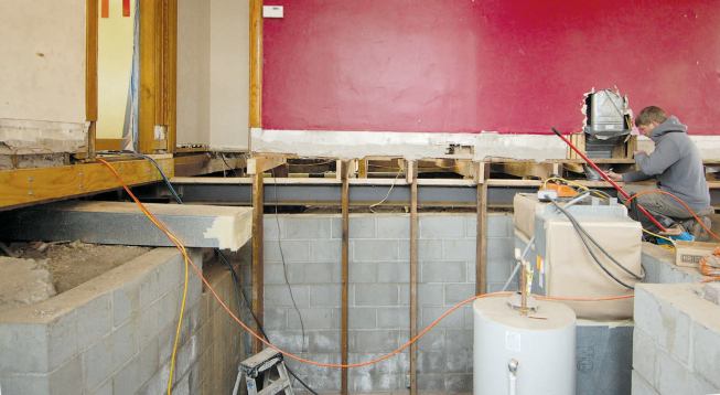
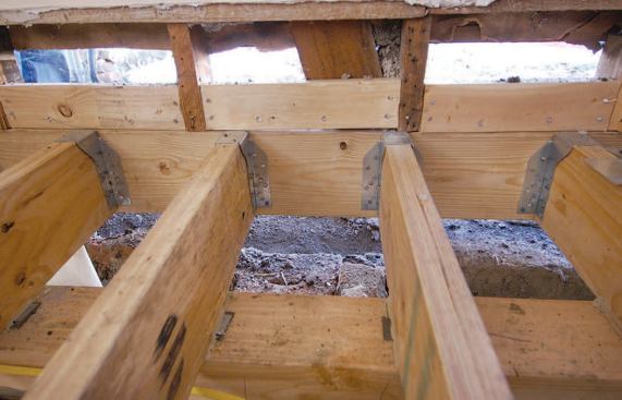
We started by removing as much of the floor system as we could while leaving the perimeter walls and existing foundation intact (see slideshow). There was no subfloor, so we stripped the wood flooring and began removing individual joists. The walls were balloon-framed, which simplified the process of removing the joists along the exterior walls. We left short sections of the joists in place under the center bearing wall, which we temporarily shored. Then we called in the helical pier contractor.
Helical Piers
Helical piers are a cost-effective way of dealing with the expansive clay common in this part of Colorado. While the piers often have to be driven fairly deep to support the loads, the process requires no excavation (for more about helical piers, see “Building a Freestanding Deck,” 12/11; “Stabilizing a Hillside Foundation,” 12/11; and Letters, 3/12).
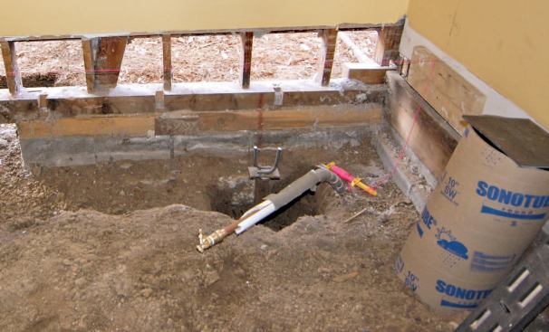
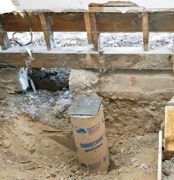
Piers are typically sized according to the soil’s type and bearing capacity. On this job, the engineer specified 6-inch-diameter single-helix lead sections with 1-1/2-inch square shafts. Extensions were added until the bearing plates were about 30 feet below grade, where the torque readout on the driver met the design loads. On most of our jobs, the contractor mounts the hydraulic auger on a skid-steer or a mini-excavator; in this case, he connected a hand-held driver to the takeoff on the excavator so the piers could be installed from inside the building. It took about a day to lay out and drive the 10 piers needed on this project, and another couple of days to cut off the steel extensions, weld on cap plates, and pour short 10-inch-diameter Sonotube piers at the top. Each pier was topped with an 8-inch-by-8-inch-by-1/4-inch steel plate set into the wet concrete.
Framing
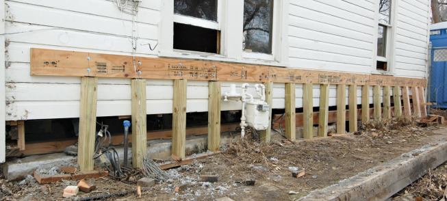
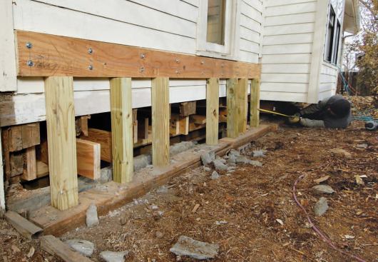
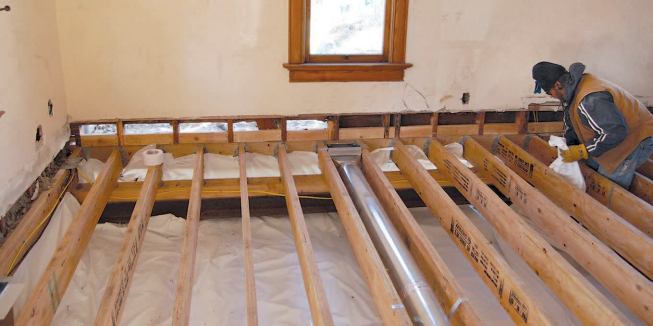
Before we could remove the old sills and start reframing the floor, we had to support the exterior walls. To do this, we bolted LVL ledgers around the perimeter of the building using structurally rated hex-head screws, two screws to a stud (see slideshow). We then laid doubled 2-by plates on the ground and cut 4×4 posts to fit snugly between the plates and the ledgers on 12-inch centers. With the building thus supported, we removed the old sills a section at a time and began cutting off the bottoms of the studs to a level line that we had marked with a laser.
Around the perimeter of the building, a specialty subcontractor …
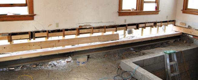
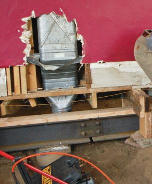
Steel girders. We installed three steel girders, capped with wood plates, to support the new floor framing. The I-beams were fabricated in sections designed to be bolted together, since getting a full-length beam would have been impossible, given the constraints of the site. Even so, this was one of the most difficult parts of the job. Sliding the steel underneath the center bearing wall was particularly tricky, because we had to do so without disturbing the temporary supports under those short joist remnants. After the steel beams were in place, we had them welded to the cap plates on the helical piers.
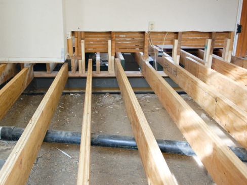
LVL joists. Next, we removed enough plaster and lath from the bases of the bearing walls to expose about 18 inches of framing. We then carefully extended the studs down to the girders, a stud at a time, pulling the temporary supports as we went and sliding the new LVL joists into position, 12-inches on-center. We used metal shims to bring each joist up to our benchmark elevation, then toenailed them to the plates. Later, we reinforced the connections with metal connectors. Finally, we fastened doubled pressure-treated 2-by rims to the floor joists, reinforcing the connection with upside-down joist hangers, per the engineer’s instructions.
Moisture Control and Air-Sealing
Before sheathing the floor, we installed a 6-mil plastic vapor barrier across the ground and up onto the rim joists, overlapping and taping the seams. Our insulation sub sealed the rims with open-cell spray foam. After installing new ductwork, we laid new floor sheathing and continued with what, at that point, became a standard renovation. Total project cost was about $90,000, which included all of the structural work, new finishes, and a new high-efficiency direct-vent water heater.
Clay Dusel is a builder in Boulder, Colo.


