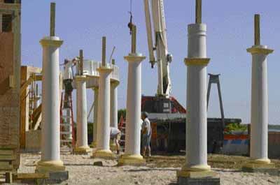
In 2003, my company built a large oceanfront home on Narragansett Bay in Rhode Island. A sheltered porch spanned the 96-foot-long east elevation, with each end of the porch topped by a conical roof. Seventeen round Tuscan-style columns supported those porch roofs. My associate, Mike Rand, supervised fabrication of the more complicated porch roof components in our shop. These included large, composite carrying beams for the porch rafters, the two conical roofs, and parapet wall surrounds for three second-floor balconies inset in the porch roof. The standard rafters would all be cut to fit on site.
Establishing Accurate Layout
We had plenty of I-joists on hand, so Mike used them to set up a full-size layout grid at the shop. The plan was to set up the grid on site — like a giant story stick — and eliminate the need for batter boards and string layout. I’ll describe them in more detail later.
Rather than laying out individual footing pads for the porch columns, we poured a continuous wide footing.
After the concrete hardened, we shipped the I-joist grid to the site and assembled it, spacing it off the building with 2×8 spreaders. We shimmed it dead straight to a laser line and propped it up level on 2×4 legs above the footings. The centerline of the I-joist determined the general center of the columns in parallel to the building. The underside of the I-joist also established the top of the concrete formwork that would support the columns.
Resisting Wind Uplift
The hollow DuraCast fiberglass columns we worked with (Dixie-Pacific, Gadsden, Ala.; 800/468-5993, www.dixie-pacific.com) are structural members with a stated load-bearing capacity of 22,000 pounds. On the other hand, wind uplift, especially under an open roof in an exposed location, is at least as great a concern as bearing capacity. Although the manufacturer suggests using small, through-bolted L-brackets as column anchors, that wasn’t suitable for this application. Instead, we used pressure-treated 4×4 posts, concealed inside the columns and connected to a concrete pier with Simpson CB44 post base hold-down anchors.
Anchoring to concrete. Mike nailed 2×4 blocking to both sides of the 1/2-inch I-joist web at each column’s center location, providing a properly sized block to hold the Simpson anchors. With the anchors held in precise position, we were able to accurately place the pier forms below, on the footing. Each anchor was also encircled by a custom-made “nipple” form, made from bendable plywood. These were nailed directly to the underside of the I-joist flange. The resulting concrete nipple would fit inside the bottom of the fiberglass column and prevent lateral movement. Rebar, grouted into the footing inside each form, provided a positive mechanical connection for the pier.
We didn’t leave any measuring for our concrete sub to do, so he was in and out in two days. We used a fairly stiff, 3,000-psi mix with 3/8-inch aggregate to fill the forms, and troweled the tops smooth.
After the concrete hardened and the inspector signed off on the work, we dismantled the layout grid and backfilled the area. We then installed the 4×4 posts using Simpson SDS screws in the base anchors. The 4x4s were 12 feet long, accounting for the combined heights of the column and the carrying beam, with some overage to be trimmed later. Setting the fiberglass columns followed immediately, so we didn’t bother bracing the posts.


