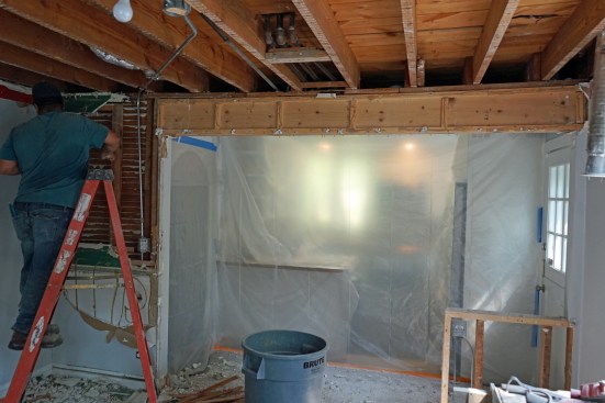
My family’s company, Great Lake Builders, specializes in structural repairs in and around Chicago. Many of the homes we work on are similar to the one shown in this article: wood-frame buildings that have outlived their structural capacity. Some of these suffered damage from badly executed floor-plan changes or from mechanical contractors hacking up the structure to retrofit new systems. And many were underbuilt to begin with. This job suffered from all of the above.
Load-Path Essentials
On this job, most of the structural problems could be traced back to breaks in the load path, which can be devastating to the integrity of a building even if it doesn’t collapse. The effects go beyond plaster or drywall cracks; they manifest in walls and floors that noticeably sag, in floors that bounce and squeak, and in doors that don’t fit their openings and shake the walls when slammed.
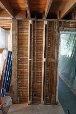
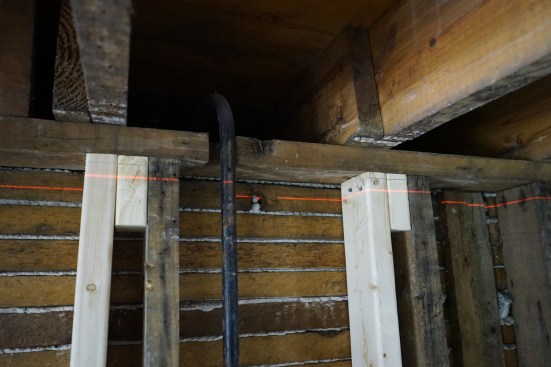
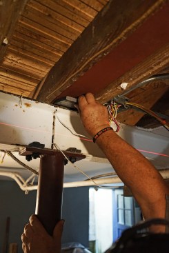
Breaks in the Load Path

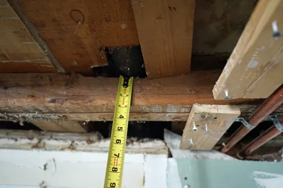
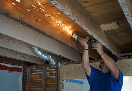
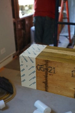
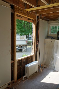
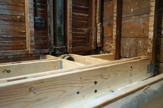
This flush beam in the second floor had no bearing on one end, o…
Loads on a building must be supported by a complete load path that effectively transfers loads “from their point of origin through the load-resisting elements to the foundation,” as it’s described in Chapter 3 of the International Residential Code. In general, the load transfer needs to be continuous from roof through walls and headers, as well as floors, beams, and columns, to the foundation. Rafters and joists should align with studs, and all load-bearing walls and floor loads must be supported by foundation walls and footings or with beams supported by columns to footings. The alignment of structural members is the best way to effectively transfer gravity loads, but the loads are not all from gravity. Lateral loads and uplift forces require connections between members that are tight (wood-to-wood) and tied securely together with fasteners. In our repair work, we hardly ever toenail permanent connections; we rely exclusively on steel clips, corners, and straps fastened with structural screws.
On this job, we were called in to execute an engineer’s design for reinforcing a number of key components in the load path (see “Breaks in the Load Path” slideshow, above). We addressed five critical areas of the structure:
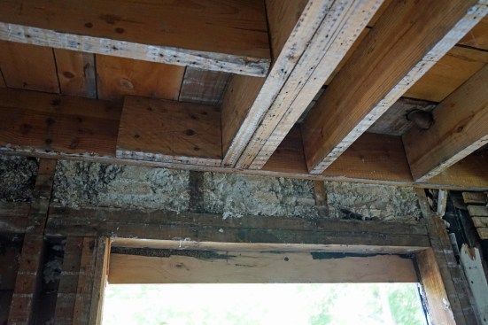
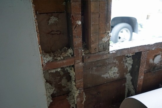
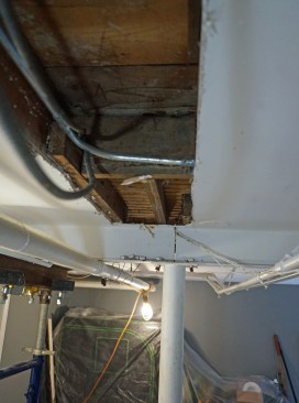
1) Undersized floor joists on the second floor had sagged. In addition, an area of this framing below a second-floor bathroom had been severely chopped up by plumbers.
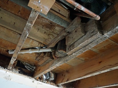
2) A flush beam in the second floor had no bearing at one end. It was simply toenailed into a ledger that was nailed to cripple studs, and the window header that picked up the loads on these cripples had no support extending to the foundation. In addition, this beam was overloaded on one side and had rolled. The framing predated joist hangers, and the end nails securing the joists to this beam had pulled away.
3) An unsupported bearing wall was failing. It was carrying the other end of the flush beam, as well as a section of the underbuilt second floor, but it had no bearing in the first floor that transferred directly to the two steel girders in the basement.
4) An undermount header that had been retrofit to enlarge a door opening into the kitchen was undersized and unsupported. This beam was in line with the flush beam. For its span and depth, the engineer said it needed to be LVL, but the remodelers who installed it had used dimensional lumber, and one end column did not have bearing that transferred to the basement girders.
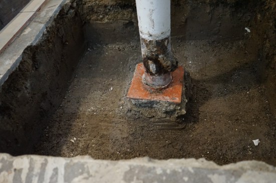
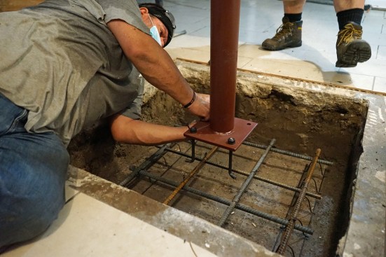
5) A steel column that supported one of the basement girders was failing because it had almost no footing.
From the Ground Up
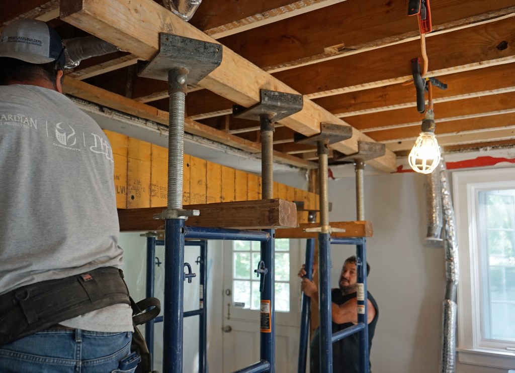
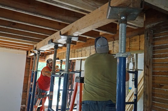
As a rule, you want to approach a load-path repair by starting at the bottom and then lift the structure from a solid foundation. On this job, we began by excavating and pouring a new column footing in the basement, so we would have a stable base to build from once we raised the structure.
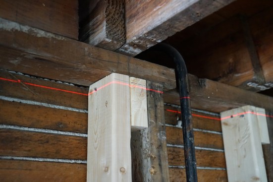
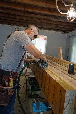
Sister Support
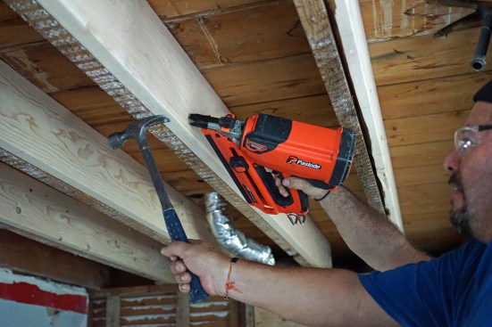
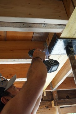
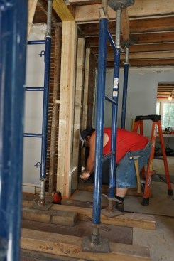
Ernesto Bonilla of Great Lake Builders cuts flooring nails so si…
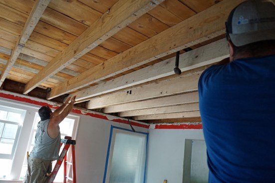
Reinforcements needed. Before jacking anything up, we first needed to sister the undersized floor joists in the second floor (see “Sister Support” slideshow, above). We wanted to create a flat floor system so that when we started to lift the structure from the basement, the floor would rise uniformly and we would be able to accurately measure our progress. This would have been impossible with the extent to which the existing floor sagged.
We also strengthened the unsupported bearing wall section mentioned above. The top and bottom wall plates had sagged at each stud, and the studs themselves were bowed. By reinforcing the wall with additional, plumb studs, we could reliably lift from below, knowing that everything would stay straight and the lifting force would be effectively transferred, raising the structure as a whole.
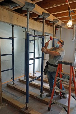
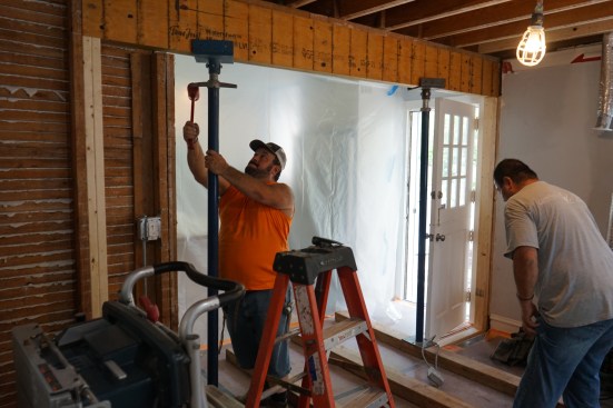
New Steel Beam
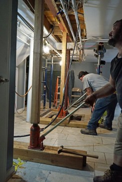

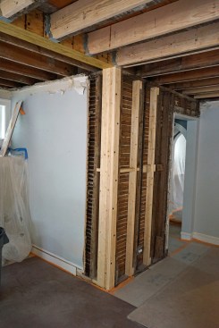
At the top of the wall section described in the slideshow above,…
Basement I- beam. Before lifting, we installed a new steel I-beam spanning between the two existing basement girders. This new steel beam was positioned directly under the previously unsupported wall section; it would support the corner column at one end of the flush beam as well as the column at one end of the undermount beam. Jacking up this new beam to level straightened the wall plates and lifted the reinforced second floor as well.
Two New LVL Beams

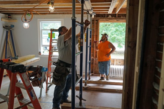
Undermount beam. Prior to removing the old undermount beam, the …
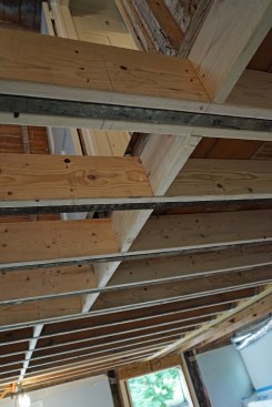
Two new LVL beams. Once the main floor elevation was established, we could install a new flush beam, built up from four LVL plies, and a new undermount beam, made from two LVL plies (see “Two New LVL Beams,” slideshow above).
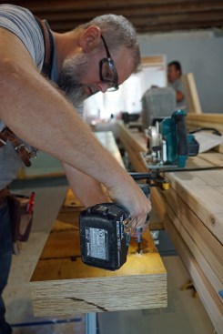
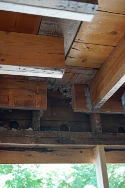
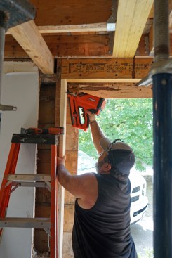
Rebuilt Floor
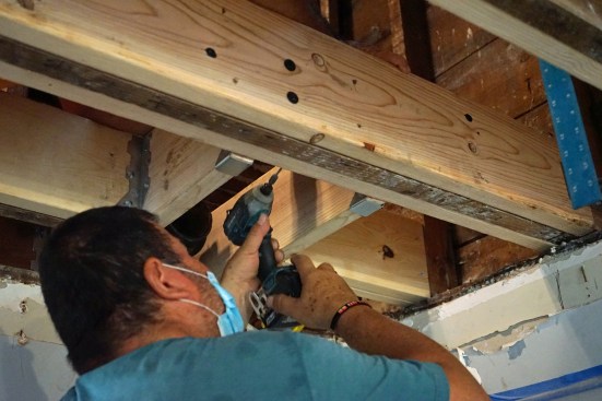

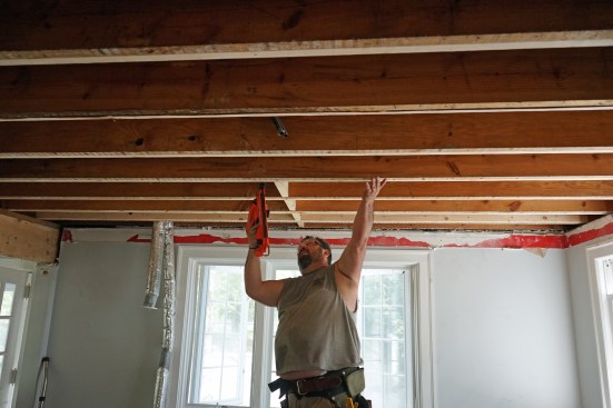
To complete the job of reinforcing the floor system, the joists…
The final step on this project was to rebuild the floor where the plumbers had hacked it up. This required adding headers across joists to carry the loads around the plumbing so we could remove the cut-up joists. It was painstaking work, as it’s difficult to screw off framing hardware in such tight spaces. Nevertheless, it’s critical to follow through with tight joints and all holes in the hardware filled with screws.
All photos by the author.


