My company recently completed the renovation of a 30-year-old raised ranch in Vineyard Haven, Mass., on Martha’s Vineyard. The job transformed a nondescript house that would have been at home in suburbia into an architecturally unique residence appropriate to its resort-island setting.
From the beginning, it was clear that one of the most technically challenging parts of the job would involve the end of the house facing the street — a drab gable with two garage doors. Determined to make this elevation into a welcoming entry, architects Geoffrey Koper and Katie Hutchison had designed a 4-foot-deep addition with a 2-foot-deep bay window seat. The bay’s four windows, set among trimmed panels and crowned with a shingled gable, would become one of the home’s nicest architectural features.
But the garage doors posed a problem. The client didn’t want to move them, because doing so would mean extending the foundation. Instead, most of the small addition would have to hang off the existing house. The question was how to support it.
The Plan
Had we been building the house from scratch, the answer would have been straightforward: Change the direction of the home’s floor joists at that end of the house so they cantilevered from the house to carry the weight of the bay. But on an existing house, this would have required a major structural redesign — which everyone wanted to avoid.
Instead, structural engineer Paul Donohue devised an ingenious way to support the bay — using steel, LVL, and solid wood — that didn’t entail tying into the existing floor frame.
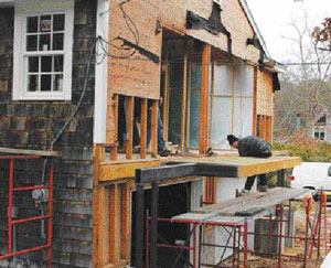
A pair of T-shaped tubular steel goalposts would be bolted to the house at each end of the bay (see illustration). The posts’ steel columns would transfer the structural load down to a 4-foot concrete knee wall extending from the existing home. An LVL header would link the tops of the two posts, and the space between the LVL and the house would be spanned with joists.
The wall and roof frame would further tie the addition to the existing home.
It was a relatively complex task, and it took me several hours with the architectural and engineering plans to understand all the requirements. Fortunately, the engineer was very helpful, and was willing to listen to my suggestions. After a couple of phone calls, we knew exactly what we had to do to make sure everything fit together properly.
The Steel
The most critical challenge was getting the concrete knee walls and steel posts right. Concrete and steel are unforgiving under any circumstances, but they’re especially unforgiving when you have close tolerances.
That was certainly the case on this job, because the floor of the small addition had to line up with the floor of the existing home.
To make sure this happened, the posts and knee walls had to be precisely the right height. And the foundation bolts in the knee walls had to be in exactly the right place, so that they lined up with the holes on the baseplates.
I spent a good amount of time measuring and remeasuring everything; rather than “measure twice and cut once,” it was more like “measure a few-dozen times so we don’t have to worry about refabricating the steel.”
Next I made a template for the foundation contractor to use in setting the bolts. This turned out to be time well-spent.
Danny Serusa, a local welding contractor, fabricated all the components of the steel posts in his shop, then delivered them to the job site and set them.
I had scheduled a half day to install the frames, but it actually took only 20 minutes. They dropped right into place.
There was some room for small adjustments. The plan called for a nut to be threaded onto each bolt before the goalposts were installed. The baseplates rested on these nuts, which allowed us to fine-tune the height of the posts with the turn of a wrench.
After the framing was completed and everything lined up, we filled the space created by these nuts with grout. The grout is what carries the structural loads.
Finishing Up
The remaining framing was nothing out of the ordinary. With the posts in place, we installed the LVL and joists, then proceeded to frame the walls and roof. Our planning paid off here, too. Since the posts had been so precisely fabricated, the wood framing required no padding or shimming. Everything went together as drawn on the plans.
We had a tougher time with the rest of the addition, because the whole house was 2 1/2 inches out of square — but that’s another story.
The engineering proved sound. I didn’t place the grout beneath the baseplates until after the framing was done and the walls and roof were in place. By that time, the addition had settled only about 1/4 inch.
I had worried that there would be some play at the end of the cantilever, but the steel-and-wood structure impressed me here, too. The outboard end feels stiff enough that you would never guess it’s hanging in the air.
Peter Marzbanian owns Marzbanian Construction in Oak Bluffs, Mass


