One of the most common structural repairs our company, Great Lakes Builders, is asked to complete is the replacement of a basement’s center girder. We’re based in Chicago, and in this part of the country, people commonly refer to this girder as the “beam line.” Here, as in other parts of the country where basements are common, the first-floor floor joists break over the girder running down the center of the basement, and it’s common to have bearing walls over this beam, as well, so it is supporting both the first and second floors. In older homes, this critical structural support is often in a poor and failing condition.
The causes for failure are many. Often, the posts supporting the beam were built on inadequate footings—sometimes just large, flat stones, or brick and mortar that eventually deteriorated in the soil. Older homes often had dirt floors and elevated moisture levels that wicked into the posts, leading to rot of the post bottoms and settling of the beam. Termite infestation of these center girders and their support posts is also common in many parts of the country.
Almost always, the beams are undersized for the current loads. In our work in high-end vintage homes, we usually see alterations at some stage of the building’s life: A new $100,000 kitchen, a living-room floor that was leveled 20 years ago, and a master bath put in with exotic tile are a few examples. Often, the alterations add significant loads, but the challenge is not always purely structural; you also need to understand the expectations of the client. Some clients think a wavy floor adds character, but others are terrified of the plaster cracking or of tile breaking. We need to know we can meet, or even exceed, client expectations before signing a contract.
In the beam-line replacement covered in this article, the 100-year-old center beam not only supported first- and second-floor loads but also supported a chimney, which added an intense point load. A cluster of posts had been added at the midspan for support, but these proved insufficient over time for the underbuilt structure. To remediate these conditions, we followed an engineer’s design to replace the wood beam with three wide-flange steel beams, each 8 to 9 feet long, for a total beam length of about 25 1/2 feet. We added two more beams, each about 4 feet long, on each side of the center beam to help carry the chimney load. All these beam sections were supported on 3-inch, schedule-40 columns with 8x8x1/2-inch base plates bolted into new 2x2x1-foot concrete footings. The photos that follow hit the high points of how we did it.
New Footing Layout and Shoring
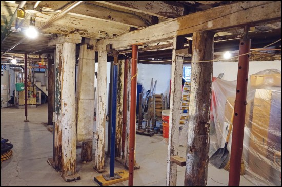
Here’s the condition of the existing beam line we found when arriving at the job. This photo shows the original wood posts clustered around the chimney location. Over time, steel “jack posts” (red), which should be considered temporary and do not meet code, had been added.
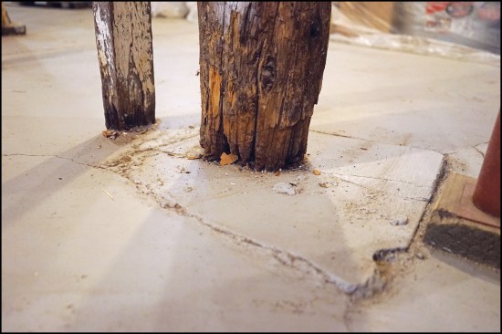
The original posts, showing signs of deterioration from wicking ground moisture, were supported on brick footings, over which a thin “rat slab” had been poured at some point to cover the original dirt floor.
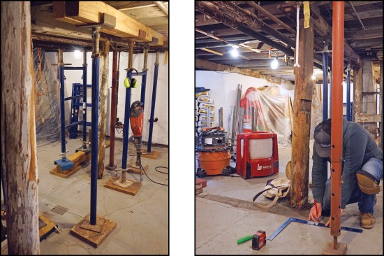
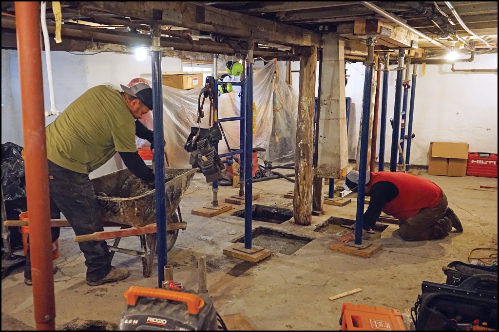
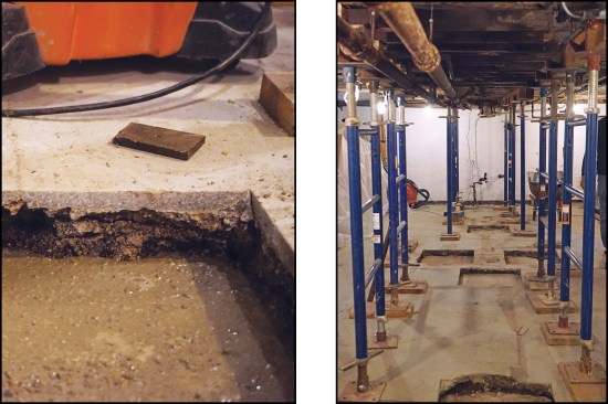
To temporarily support the load, we added two lines of heavy-duty shoring running parallel to the beam line (above left). In this case, we were not jacking the floor, only supporting the floor at the existing elevation. Before installing the shoring, we measured where our new footings would be placed, keeping the shoring lines out of the way. Once the shoring was in place, I began to lay out the footing locations, using a laser to reference the centerline of the main beam (above right).
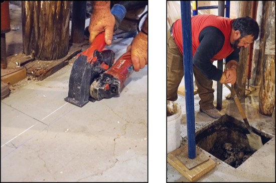
With the beam line marked and the footing locations defined, the crew cut through the slab to place new footings. We cut through the existing slab, which varied in thickness from 3/4 inch to 1 1/2 inches, with a small grinder outfitted with a vacuum shroud (above left). Once the perimeter of each footing was cut, we broke the slab out and dug the footing holes to a depth of about 15 inches (above right).
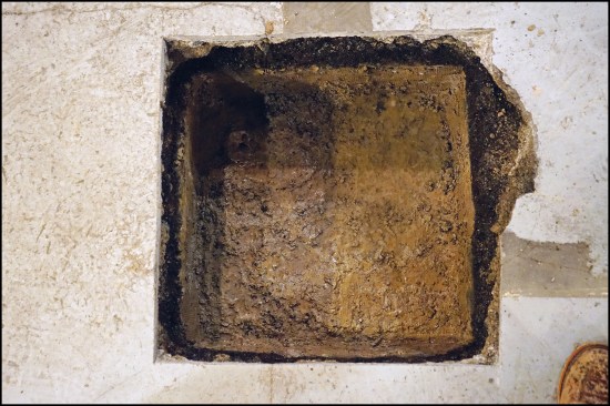
For each squared-off footing hole …
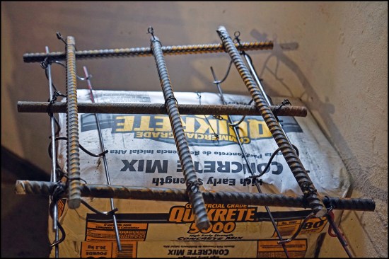
… we wired together a grid of #5 rebar (specified by the engineer), including rebar chairs that held the grid 3 inches above the bottom of the hole.
We poured each footing to a depth of 12 inches, well below the slab elevation (above left), allowing us to finish out as shown on the last photo. We used a “high early” Quikrete 5000 mix, which rapidly cured to 3,000 psi in a few days (above right).
New Steel Beam Line
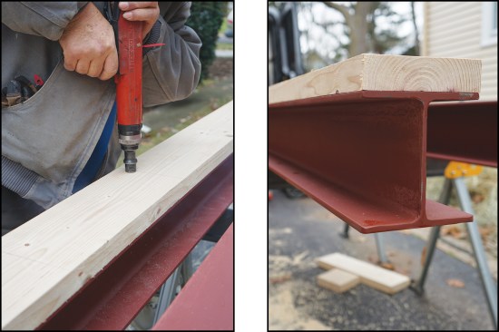
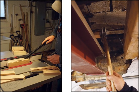
While the footings were curing, we prepared the steel I-beams, pinning a wood plate (above left) to the top of each beam section (above right) with a powder-actuated tool. This 2-by nailer allowed us to mechanically fasten the beam to the joists, which would keep the joists from rotating. It also allowed us to adjust the elevation of the beam by mortising the plate rather than by removing material from the existing joists.
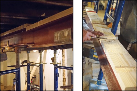
We rough-fit the beams (above left) to mark the joist locations on the plate and measured the depth of the mortises we needed to cut. Each mortise was a different depth to accommodate the variation in the elevations of the joist bottoms (above right). On this job, the client did not want our work to cause any cosmetic damage to the finishes in the house above, so we were careful to support the floor at the existing elevation.
With the mortises cut, the variation in the bottom elevation of the joists was apparent. Such variation in joist size is common in older homes. When the house was framed, lumber dimensions varied more than we typically see today, and the carpenters were only concerned with having the tops of the joists at the same height.
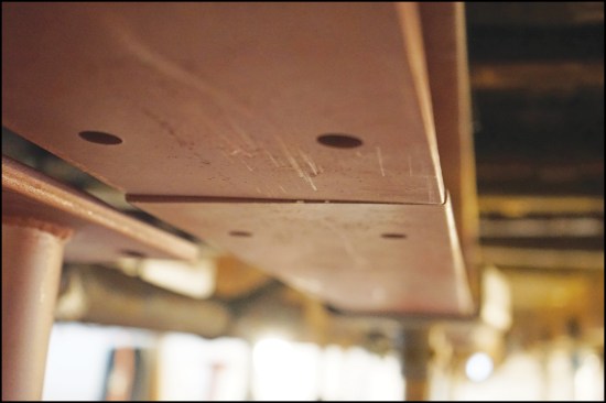
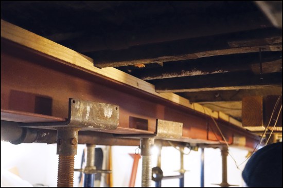
Once the mortises were cut, the beam sections aligned to within 1/16 inch or so; they would be pulled into perfect alignment when the post was bolted in place.
The bottom of some joists would be higher than the 2-by plate. For those, we cut shims (above left) that we pounded into place where needed for firm bearing (above right).
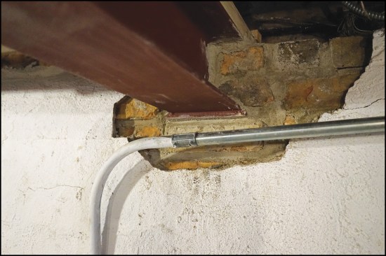
One end of the new beam had to be grouted into a pocket in the foundation. This required enlarging the original beam pocket for the new steel beam, including a 7x7x1/2-inch setting plate specified by the engineer to spread the load at the foundation.
Patching the Slab
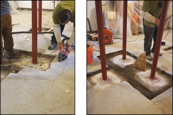
With the post base plates bolted to the new footing, the crew focused on cutting away the slab (above left) in order to join the footing area of the three posts supporting the chimney and midspan. Once the old slab was removed, the footings were broomed clean in preparation for a new pour (above right). The goal here was a clean fit and finish of the new work, with the post bases recessed below the surface of the existing slab.
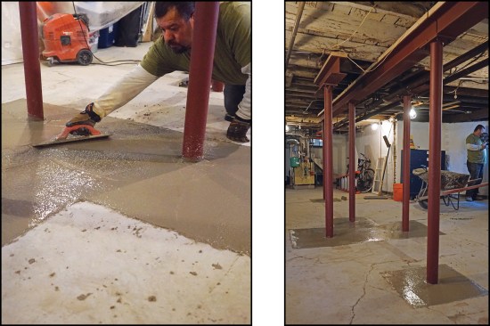
The slab area around the two end posts was also widened, then all three areas were covered with a new, thicker (3‑inch) slab. After the surface was finished (above left), the result was clean—better than the existing slab (above right). While the structural elements of our new work are of critical importance to us, in the end, what the customer will see is how clean it looks. And there is no doubt on this point here.
Photos by Jake Lewandowski.
Got a Comment?
Click here to submit a Letter to the Editor. We value all comments, corrections and questions.
If we think others will benefit, we may publish it in print. Letters should be exclusive to JLC, Professional Deck Builder or Tools of the Trade. We do not publish open letters or third-party letters. Writers of letters selected for publication will be notified. Letters may be edited for clarity and shortened for space.


