Recently, my company built a new home with a two-story screened porch that had some interesting radius features. The main structure for the porch consisted of bent or rolled steel I-beams. Because we work on the coast, most new houses we build include some steel, whether for its superior strength for supporting a large floor or roof load, or for its ability to resist lateral wind forces. But this was my first go-around with steel beams formed into a circular shape.
The structural engineer and architect designed the rear porches with a half-round steel drop beam to support the second-floor porch, and an additional half-round beam at plate height to support the rafters of the conical roof over the porch. Three 5-inch square columns made from 1/2-inch steel provide vertical support for the two half-round steel beams and the rest of the porch structure. These columns run full height to the underside of the upper beam, with the lower beam cut at the middle of the curve and attached to the columns via welded steel tabs called flag connections. The upper beam is bolted to steel plates welded to the tops of the columns.
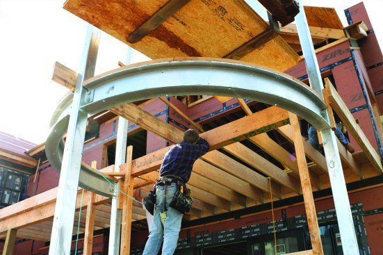
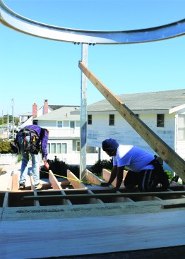
After laying out the curved beam directly on the first-floor slab, the author drew a full-size pattern on lauan plywood to help guide the metal fabrications
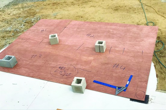
The porch columns would attach to the metal plates embedded in the slab.
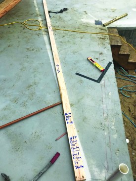
The author also made a story pole to record the heights of the two radiused beams, as well as the differences in the column heights due to the drainage slope of the slab.
Curved Layout
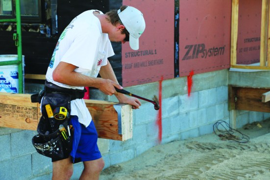
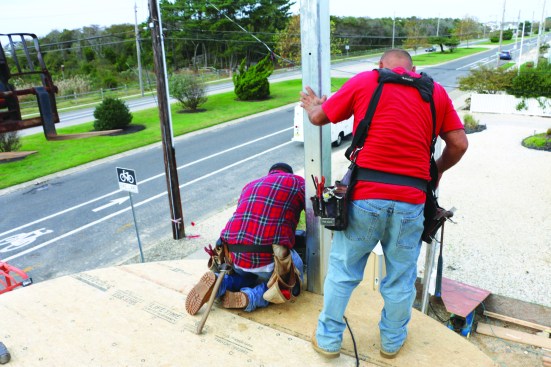
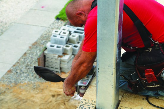
As with most construction projects, building the curved porch began with laying out its location at the early stages of framing the house. The columns would need to be welded to steel plates embedded in the concrete slab for the first-floor porch, so prior to pouring the slab, we laid out the locations for the steel plates and gave the mason their dimensions and references off the building. He then built piers from stacked masonry chimney block inside the curved foundation wall to support the point loads from the columns.
Once the porch slab was in place, I drew the radius and the width of the beams on the slab. Knowing that the fabrication of the steel parts would take several weeks, I sprayed clear lacquer over the pencil and chalk lines to preserve them from the elements. Next, I made a template for the steel fabricator. A scaled drawing probably would have worked fine, but I prefer to make a full-scale pattern any time I need to involve a subcontractor to fabricate something as complex as this steel frame. For this project, I transferred the layout onto sheets of 1/4-inch lauan plywood. My local steel fabricator then delivered the pattern to another fabrication shop in northeast Pennsylvania with specialized equipment capable of rolling the W10x26 I-beams into the circular shape.
At the layout stage, I also created a full-height story pole—20 feet tall—for the column and beam heights. On the story pole, I indicated the locations and full height (10.33 inches) of the W10x26 beams. Because the first-floor porch slab was pitched for drainage, the three columns would be different heights, so I also indicated those differences. The north (center) column was to be full height, while the west column needed to be 7/16 inch shorter and the east column 1/4 inch shorter than the north. These adjustments allowed the beams to sit level once the posts were welded to the plates, and the differences in measurement were given to the fabricator to cut the columns accordingly.
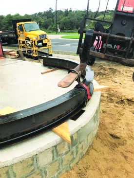
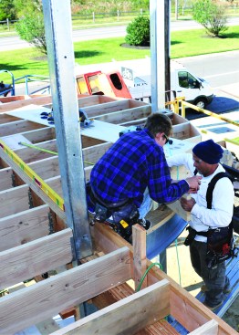
The steel fabricator sent out the beams to be rolled into the curve, then brought them to the site to check the layout and mark column positions on the top of the beam.
The Steel Frame
Four weeks later, the steel fabricator brought the radiused beams to the jobsite, but at that point, the beams had just been roughed out. To verify that the curve of the beams was very close to what I had laid out on the template, we set the beams on blocks over the layout lines that I had made on the slab earlier, then we transferred the column locations onto one of the beams for completing the beam and column fabrication. We were also careful to label the direction and orientation of the beams so that nothing could be flipped around during handling.
The fabricator then returned to his shop to fabricate the columns, to cut beams as needed, and to add welding flanges and flags to the columns. Also, I opted to have the fabricator galvanize the columns and beams. Even though exterior trim material would encapsulate the structural steel frame, I worried that the marine environment would rust the components and eventually stain the ipe decking and silver travertine patio material. Galvanizing added a bit of time to the fabrication, but it was needed to ensure the longevity of the structure. Three weeks later, the steel fabricator delivered the components for the frame, in pieces. His crew then assembled the structure without fully tightening the bolts, to allow for minute adjustments once the steel frame was standing.
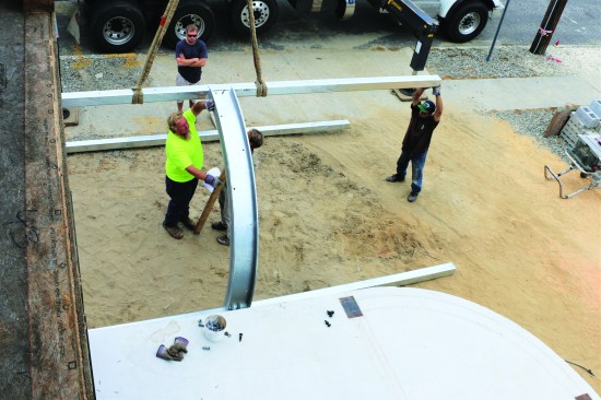
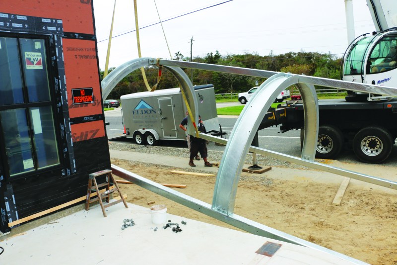
After finishing the remainder of the prep work, the fabricator brought the metal parts back to the site for assembly.
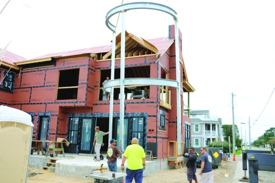
With the connections kept loose for adjustment, a crane raises the frame and sets it on the slab.
The fabricator tack-welds the bottoms of the columns to the steel plates to keep them in place during adjustment.
After the frame was assembled, a crane lifted it to a vertical position on the slab. After placing the columns on my soapstone layout marks on the welding plates, the ironworkers tacked down the columns. We also braced the frame back to the building. Plumbing each of the three columns in two directions was a bit of an ordeal, and when the frame was finally plumbed and braced, the crew permanently welded the columns to the plates and tightened all of the bolts joining the columns to the curved beams.
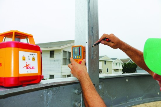
After bracing the frame and tightening the connections, the author sets a laser on the beam to lay out the ledger on the house.
The crew marked and labeled all the lines.
Second-Floor Deck Layout
With the steel frame welded in place, we were ready to frame the second-floor deck. The curved part of the deck joined a rectangular deck that continued over to an intersecting volume of the house. As I typically do, I began by stapling an 18-inch-wide rip of felt paper onto the wall sheathing of the house at approximately the same height as the deck ledger. The building paper gives me a good surface for laying out the ledger, and later in the process, I’m able to integrate the paper with the WRB below the deck as I side the house.
Then they snapped a chalk line for installing the ledger.
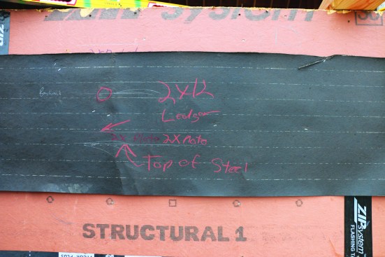
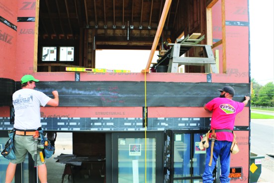
After placing my rotary laser on top of the lower curved beam, I made some level reference marks on the felt paper for the deck-ledger locations. From there I accounted for the offset for the height of my laser and made marks in red keel to indicate the top of the steel, the top of the 2-by plate, and the top of the 2×12 ledger. With the help of a crew member, I snapped blue chalk lines on the felt to set the bottom of the deck ledger.
Framing the Curve
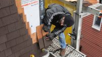
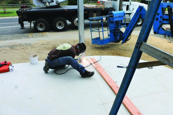
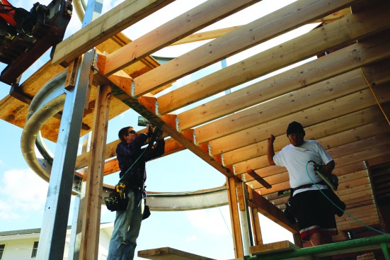
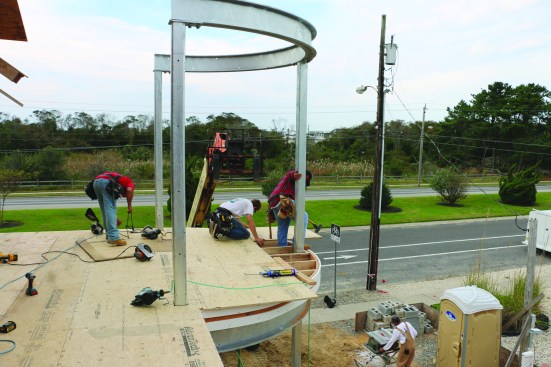
While the crew installed the ledger for the deck, we plated the top of the curved beam with short lengths of 2x12s. We held the pieces in place on top of the beam and scribed the curve for both sides of the beam. We cut the radius with a circular saw, making a series of passes along the curved line. As each plate section was finished, we fastened it temporarily in place with powder-actuated pins. Later, we through-bolted the plate to the steel beam.
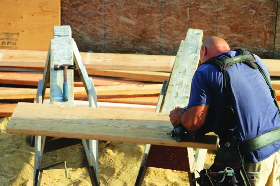
Using a series of cuts made with a circular saw, a crew member cuts the plates to go on top of the curved steel beams.
The curved plates were tacked in place with powder-actuated fasteners (12), then through-bolted to the top flange of the steel beam.
An LVL drop beam that extends from the house to the west column of the curved porch supports the joists for the rectangular part of the deck. The joists for the curved porch hang from an LVL flush beam that spans between the east and west columns. That flush beam breaks up the joist framing, with regular joists running from the flush beam to the ledger on the house, and joists for the curved section extending from the flush beam out over the curved plates that we’d just finished installing.
A crew member nails concealed-flange hangers to the flush beam.
The flush beam was braced between the columns for framing the deck. Later, the hangers were welded to the columns.
Before the flush beam was installed, a crew member attached concealed-flange joist hangers on the ends of the beam. (The drop beam for the rectangular section had received the same treatment on the end that attached to the steel porch column.) Instead of the nailing flanges extending out to the sides, they wrapped around the end of the beam. After lifting the beam into place with the telehandler, we supported it with temporary props that we kept in place while we framed the floor. Later, the ironworkers came back and welded the concealed flange hangers to the steel columns, and we removed the temporary bracing.
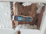
A 2-by block was tacked between the middle two joists.
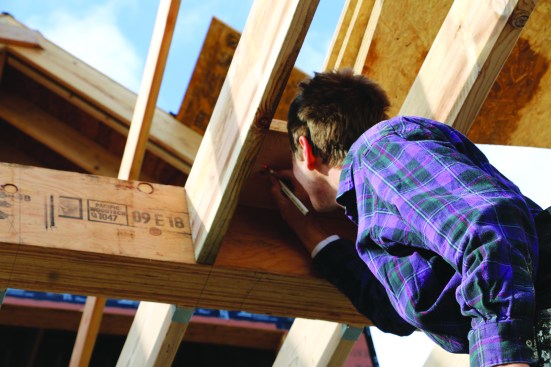
It catches the laser light from the pivot point on the slab below.
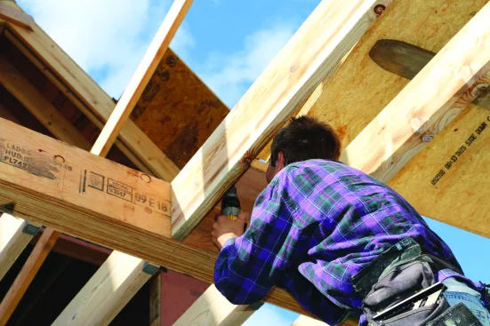
Drilling through the block transfers the point to the top of the block.
After dropping in the common-length deck joists between the ledger on the house and the flush beam, we were ready to cut the joists for the radius section. We set two joists at the center of the curve, letting them run long over the curved plate, and then installed a 2-by block between the joists at the flush beam. Using a laser, we plumbed up from our original pivot point on the first-floor slab and made a mark on the underside of the 2-by block. We drilled through the block and pushed a nail through the hole to transfer the pivot point to the top side of the 2-by. That nail gave us a radius point for cutting our joists to length.
This allowed for marking the radius on the joist ends.
Perpendicular blocking supports the outer edges of the plywood rim joist.
We installed the rest of the joists for the curved section, letting them extend out past the curved plate. Then one crew member held the end of the measuring tape at the pivot point while a second crew member scribed the length and the angle of each joist. Then it was just a matter of setting the saw to the proper angle and cutting the joists to length. To support the outermost joist bays, we attached perpendicular blocking to the adjacent joists. The blocking kept the amount of unsupported rim to a minimum.
Sheathing the Curved Floor
When the joists were all cut to length, we installed three plies of 1/2-inch CDX plywood that bent easily around the curve of the joist ends. We staggered the seams between each layer, nailing the plywood to the ends of the joists and the blocks. To fair out the curve for the finish fascia, we nailed two bands of PVC over the plywood.
The rim joist consists of three layers of 1/2-inch CDX plywood, followed by an upper and lower band of 1×5 PVC to even out the curve.
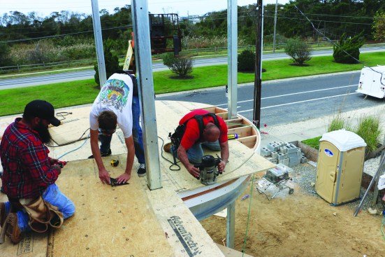
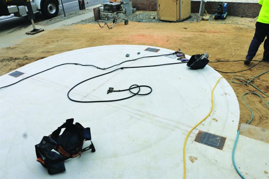
To provide the base for the waterproof fiberglass layer that will protect the areas below the porch, the crew nails down OSB subfloor, routing the curve around the perimeter with a bearing-guided bit.
To provide optimal protection for the screened-in porch areas on the first floor, plans called for the second-story porch floor to be waterproofed with fiberglass using the methods described in my article “Fiberglassing an Exterior Deck” (Feb/16). The finished porch floor would consist of ipe decking installed on treated wood sleepers on top of the fiberglass. Because the fiberglass waterproofing layer requires a solid subfloor, the crew installed AdvanTech’s moisture-resistant 3/4-inch OSB panels over the deck joists, extending the subfloor panels out over the rim joist. As we worked, we trimmed off the radius using a router with a bottom-bearing bit. The final piece of subfloor wrapped around the north post. After completing the subfloor, we belt-sanded the edge to smooth out the curve in preparation for the fiberglass waterproofing layer.
The final piece of subfloor was fit around the outer column.
Then a crew member smooths the edge of the cut sheathing with a belt sander.
With the subfloor installed, we set up scaffolding to build the conical roof over the second-floor deck. The fiberglassing and finish details for the round porch were done after the house was weathered in.
Photos by Nathaniel Eldon