Lee McGinley
I then snapped a line 4 inches in from the edge of the uphill ti…
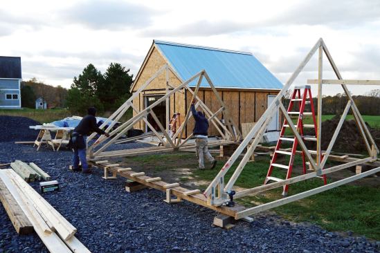
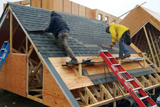
My least favorite part of house building? Easy call: the roof. While I enjoy the challenge of working complex layouts—such as skewed roof intersections at different pitches—typical trussed roofs present few intellectual challenges or aesthetic compensations. Given the risks involved with wrestling with heavy materials in high winds far above solid ground, I’d rather pass. Then it occurred to me that my crew and I could eliminate the danger and discomfort of framing and shingling a roof by doing everything on the ground. I was more than a little excited by the idea.
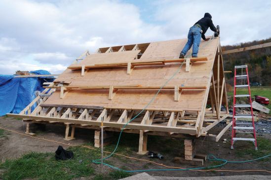
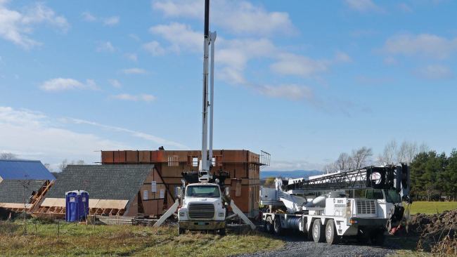
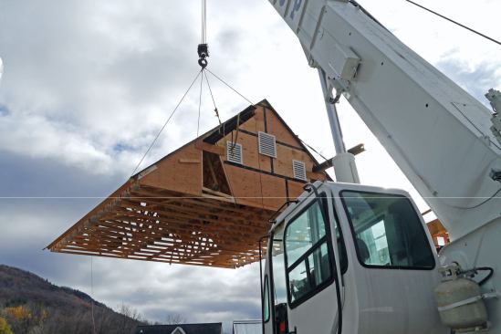
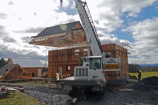
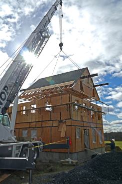
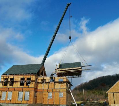
With frigid weather fast approaching our area in northern Vermont, I was also eager to use a method that would save time. And this particular roof was a good candidate for this somewhat novel approach: Stack the trusses on the ground, sheathe and roof the structure, then lift the whole assembly using a crane. The house was a new two-story, 26×28 with a 20×20 ell, built on a relatively flat site. It had two roof sections, each with a 10/12 pitch and simple trim details; there were no fancy overhangs on the rake or eaves, only flat trim that could easily be installed later while clapboarding the house.
Frame, Roof, Lift
A local crane operator assured me that my project was “doable” and that I need not worry about his equipment distorting the roofs or otherwise causing them to need remedial work. He told me where to position the roofs in relation to the house to facilitate the hoisting.
I broached my plan to the two carpenters working with me. They were enthusiastic about not having to lug materials and equipment up two stories, and of course the safety aspect was important to them, too. We all recognized that when working in easier conditions on the ground, we would be less tempted to take shortcuts that might compromise quality than we would be when working higher up.
I knew precision layout would be important, but that wasn’t a serious concern because my crew consistently frames to 1/8-inch tolerances. Some research led me to the next essential: a roof-truss manufacturer that could deliver a consistent product. High quality was critical because we would need to factor in some “wiggle room” so that the trusses could be set atop the wall framing with enough clearance that we could finesse them into alignment.
Preparations
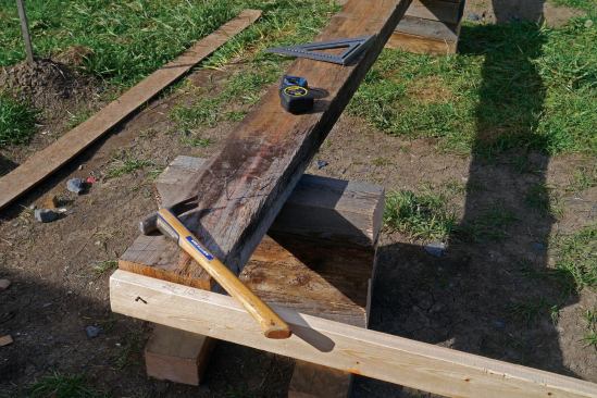
Trusses ordered, I sourced rough-sawn 4×8 and 6×6 timbers locally. They would be the “runners” on which we would set the trusses.We framed each roof section separately, beginning with the smaller one. The site had a slight downward slope, so I placed one row of the rough-sawn timbers on the uphill side, extending each end about 3 feet beyond the planned length of each roof. I elevated this row about 1 foot above grade using jobsite scraps.
Next, I placed a second row of timbers parallel to the first, spaced 2 feet narrower than the width of the trusses. I tied the ends of each set of timbers together with 2x4s so they would stay parallel. With a helper, I shot elevations and leveled the timbers, keeping to our 1/8-inch standard.
I then snapped a line 4 inches in from the edge of the uphill timbers. Measuring across to the downhill timbers, I snapped a second, parallel line. These parallel lines, marked out on both sets of runners, served as reference points.
Each set of runners was longer than the length of the roof it would support, so I arbitrarily marked a point 2 feet in from one end of each row on the uphill timbers. From that point, I measured the length of each roof: one at 20 feet, the other at 26 feet.
Knowing the distance between the parallel lines on each row and the length of each roof, I calculated the hypotenuse. Using two tapes, I located a third point on the snapped line of the downhill row. The fourth and final point was located by measuring the length along the snapped line. I checked my triangulation by beginning at opposite points. Now I had a perfectly square footprint. With eight man-hours invested in setting the timbers and layout, we were ready to frame.
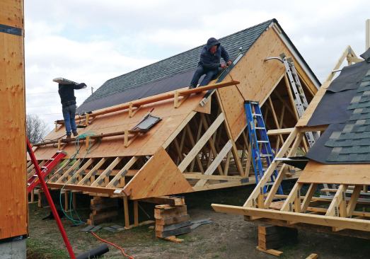
Framing
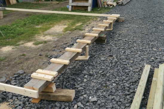
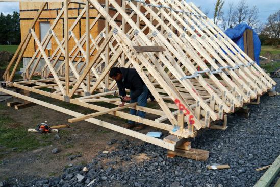
We laid out the trusses along the snapped lines and nailed 2×4 blocks perpendicular to the lines to serve as stops for the trusses to bump against as we set them.
Since the smaller (20×20) roof was built several feet from a new garage, we braced the first gable truss to that, then set the remaining trusses using Simpson’s Spacer Bracers (strongtie.com) at three points along the top chord. We aligned the end of each bottom chord 8 inches from the snapped line on the uphill timbers.
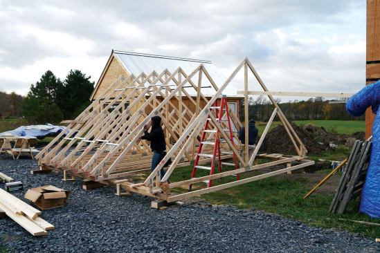
We checked for plumb and verified the on-center layout, then nailed on the lateral bracing required by the truss manufacturer. Down the middle, I nailed two 2×6 catwalks to facilitate blowing in loose-fill insulation. We also stiffened the assembly by nailing on 2x6s 2 feet in and parallel to the ends of the trusses. Cross-bracing the truss webs also stiffened the assembly. I checked diagonals along the roof plane on both sides of the roof and they were right on.
The gable-end trusses were the same design as the common trusses so the steel rails used to raise the roof would apply uniform pressure on the roof. The gables were sheathed on the ground, with cutouts where the rails would slide into place. Two-by nailers backed up plywood seams; mending plates were secured behind to strengthen the connection.


