In the previous issue of JLC, I wrote an article describing the process that our crew typically follows when snapping accurate layout lines for the exterior walls of a house (“Layout Lines for Exterior Walls,” Apr/16). That procedure took two lead carpenters only about 30 minutes. While the rest of the crew continued to chip away at their prepared lists—cutting cripples, jacks, and studs and assembling headers, corners, and partition studs—the same two lead carpenters started on the next step: cutting and laying out the wall plates.
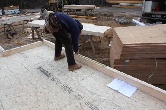
The first task was setting up a cutting station for the plates. For that purpose, two heavy-duty sawhorses were set up in a central but out-of-the-way location on the first-floor deck. A lift of 16-foot 2x6s labeled “plates” had come from the lumberyard, and the crew loaded a few dozen of those boards onto the sawhorses. As they went through the pile, they set aside warped or twisted boards, keeping only the straightest boards to use as plate stock.
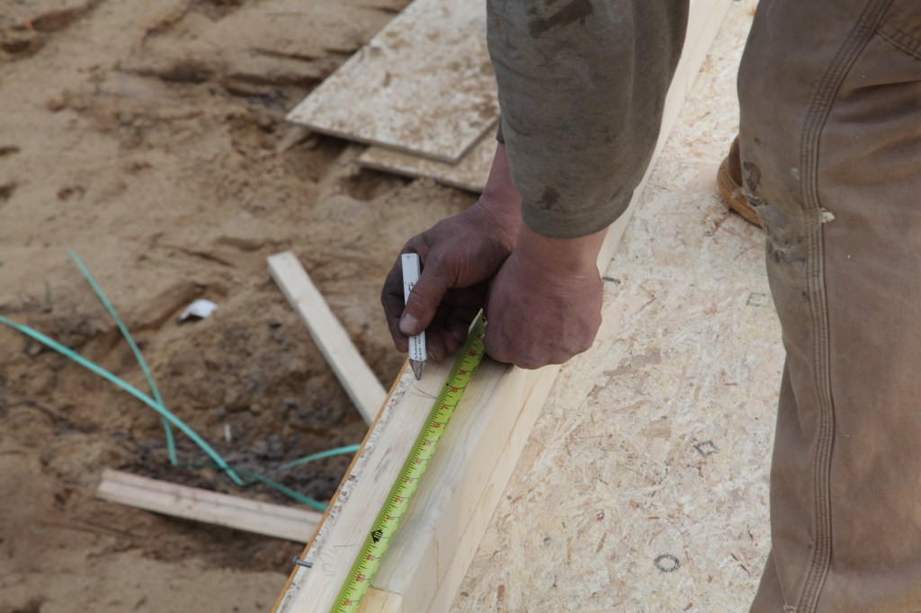
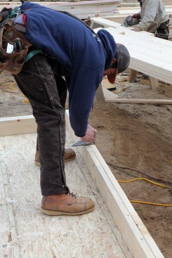
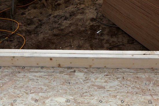
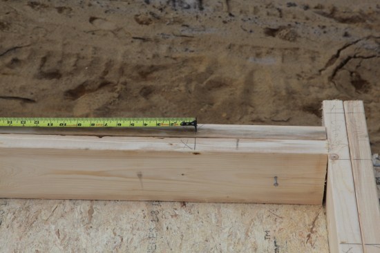
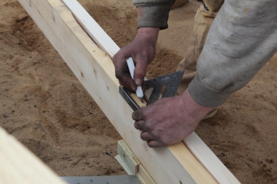
Before plates are measured and cut to length, one end is cut square. Measurement is then taken from that end.
Square the Stock and Cut to Length
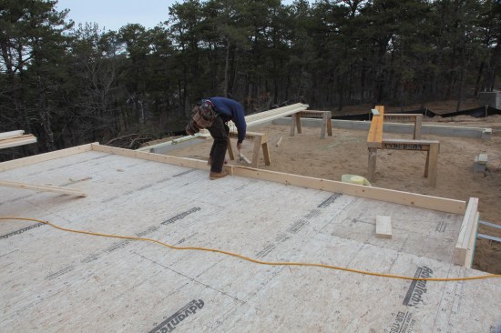
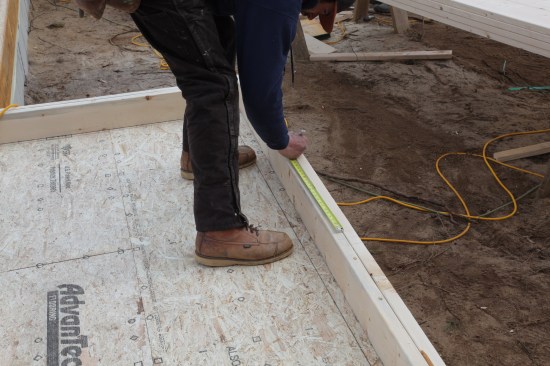
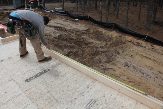
Once the stock is loaded and ready to go, two crew members start laying out plates on opposite sides of the house (to stay out of each other’s way). They take measurements directly from the wall layout before measuring and cutting the plates to length.
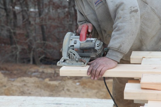
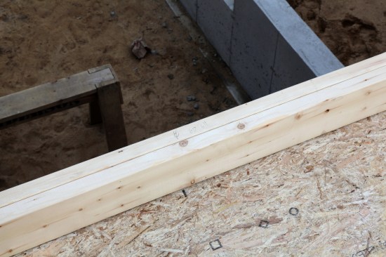
When the walls are shorter than the plate stock on site, the plates are measured and cut in pairs. After they are cut to length, the two boards are tacked together.
After the boards are tacked together, the pair is set in place on the perimeter of the deck where the wall will be built.
Framing stock rarely comes from the supplier with perfectly square ends, so we always saw one end of the board square before we cut it to length. We pull our measurement from the squared end and cut the plates to length. If the length of the plate is less than the length of the stock, two plates (top and bottom for the wall) are cut and tacked together at each end. We then place the paired plates on the deck where the wall will be built.
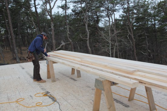
When the wall is longer than the plate stock, both ends are squared on two lengths—one for the top plate and one for the bottom. The boards are then set in place with one end of each board set on the layout line and the two boards overlapping in the middle. The boards are tacked together at the overlap.
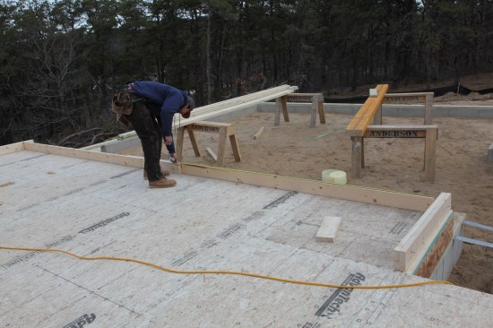
Next, a measurement is taken from the end of each board to the overlap to obtain the lengths for the boards that will fill in the rest of the top and bottom plates. Those boards are then cut and tacked in place.
If the wall is longer than the plate stock we’ve been given, we square both ends of two lengths of stock—one for the top plate and one for the bottom plate—and then set the boards in place with one end of each board at an end of the wall and the other ends overlapping in the middle. After aligning the ends exactly on the layout lines, we tack the two pieces together at the overlap. Then it’s just a matter of measuring from each end to the overlap and cutting the fill-in pieces to complete both plates. We use a second top plate, so we never try to break the plates exactly over a stud. In fact, I’ve been told that nailing the ends of two plate sections to the same stud can create a weak point in the framing.
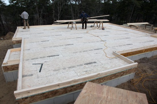
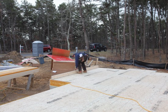
Plate measuring and cutting proceeds until all the wall plates are cut and set into place.
We usually don’t start the actual layout until all the plates are cut and set in place around the perimeter of the deck. To keep the framing consistent throughout the house, we always pull layouts from the same point. This keeps the framing members aligned for direct load transfer from the rafters all the way to the mudsills. For this house, we used the side of the house opposite the garage and the back wall of the house as starting points for the layout.
Lay Out the Rough Openings First
The openings for doors and windows are the first items to be laid out. Close attention must be paid to exactly what the dimensions on the plans refer to. Sometimes they denote the distance to the centerline of opening, and other times the measurements on the plans are to the center of an architectural element of the house. For example, the dining-room slider on the rear of this house was centered on a screened porch. An open deck next to the porch became the centering element for a double kitchen window. Dimensions given on the plans were for the porch and the deck with indications that the openings be centered on those elements.
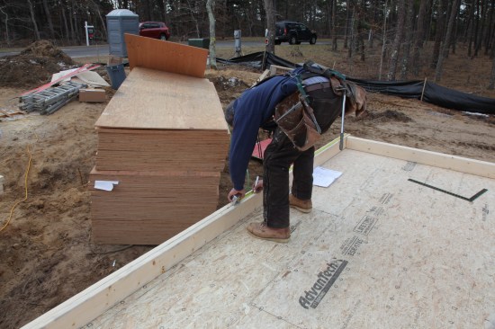
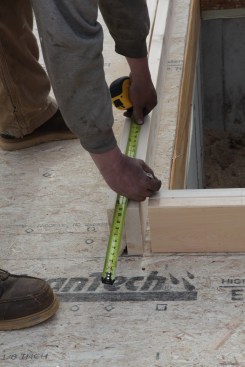
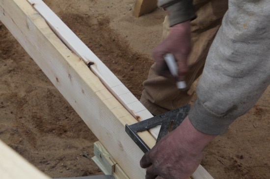
The first things the layout crew marks on the plates are the openings. Here the crew member measures to the middle of the wall, which is the middle of a center window.
On this wall, the middle window is flanked by windows on either side. After marking the center of the middle window, he measures over and marks the sides of the rough opening for that window.
On the front of the house, a triple window was centered on the living-room wall, with the three windows separated by double 2-by stud pockets. The crew member doing the layout pulled the initial measurement from the side of the house (in this case, the end of the wall) and marked the centerline of the wall, which was also the centerline of the middle window. The rough-opening (R.O.) dimensions for each opening had already been noted on the plans, so next he marked out the R.O. width of the center window. Using a layout square, he drew lines for the stud pockets and then measured the R.O. width of the side windows (9), drawing a square line to mark that opening.
After marking the stud pocket (the doubled stud between the windows), the crew member measures over for the rough opening of the side window.
The layout crew member then draws a square line across the plates for the other side of the rough opening of the side window.
The carpenter doing the layout also writes the R.O. dimensions either next to the centerline or in some conspicuous place within the opening. These dimensions correspond to the list of headers, cripples, and jacks that the rest of the crew is working from. When we’re ready to “load” the lumber for each wall, we can just go to the various piles and grab the framing member that has the same dimensions that are written on the plate.
After the openings are laid out, the rough opening measurements are written on the plates in the opening to help facilitate wall building later.
Special Wall Framing Elements Are Next
With the openings roughed out on the plates, the layout crew turns its attention to the framing around each opening. This house was being built on Cape Cod a short distance from the Atlantic Ocean, and the plans called for prescriptive high-wind framing with doubled king studs and jacks for each opening more than 5 feet wide, and tripled kings and jacks for openings more than 7 feet wide. The layout crew marks out the required king studs and jack studs on each side of the opening depending on its width.
Then, the king and jack studs for either side of the opening are laid out. This house was being framed in a high-wind area, so many of the framing members were doubled or tripled depending on the width of the rough opening.
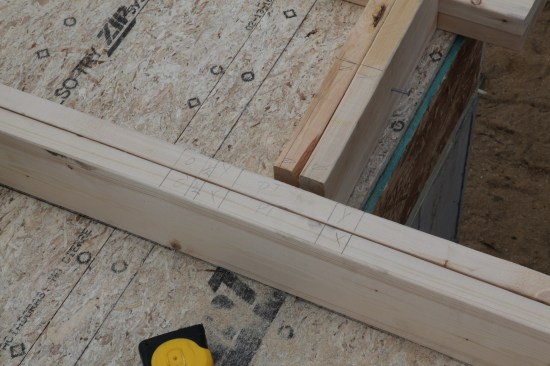
The next things to be laid out are the partition backers, where intersecting walls are attached. For 2×4 walls, the backer is drawn as a stud with another line 5 1/2 inches away. For the 2×6 wall backer shown here, the framing is drawn as two studs 5 1/2 inches apart.
Next, we locate the partition backers for intersecting walls. We build a backer as an L-shaped assembly made from a 2×6 stud with an attached perpendicular 2×6. For the layout, we draw a stud with a 5 1/2-inch space next to it. Again, the locations of the interior walls are spelled out on the plans, and the layout crew measures and marks those locations on the plates. Close attention is paid to the size of the intersecting walls. Most interior walls are framed with 2x4s, and for these walls, the 2×6 L-assembly provides ample drywall nailing for both sides of the wall. If the intersecting wall is framed with 2x6s, as are the exterior walls of the fireplace bump-out, we make the partition backer as a U-shape. It gets laid out as two studs with a 5 1/2-inch space in between. An example of an interior wall framed with 2x6s is a wall that houses plumbing.
The last pieces of specialty framing to be marked out on the plates are the corners. There are many different techniques for framing corners, but we usually build U-shaped corners unless requested to do otherwise. These corner assemblies are installed on the ends of the walls that extend past other walls.
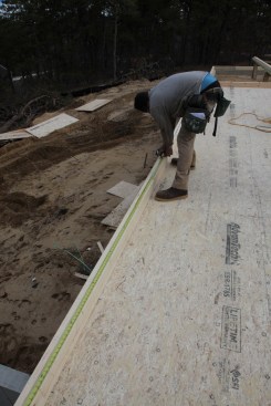
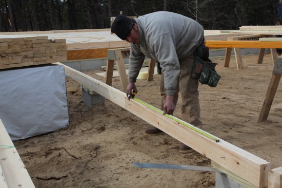
Last to be laid out are the studs. Here a crew member pulls the layout from the end of the wall and marks every stud, including those that fall in the openings for the doors and windows.
Studs Are Last
With all the wall elements finished, the final layout items are the studs. Again, the crew member pulls the layout from the designated point and marks out the studs at the proper spacing. For this house, the 2×6 studs were spaced 16 inches on-center. Pulling the layout from the end of the house, the stud layout is marked 3/4 inch to one side of the 16-inch increment highlighted on the tape.
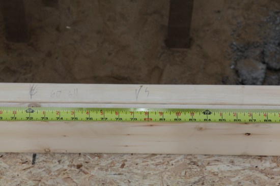
To make the studs line up 16 inches on-center, the layout is marked 3/4 inch (or half the thickness of a 2-by stud) to one side of the highlighted mark on the measuring tape.
That marks the edge of a nominal 1 1/2-inch stud on a 16-inch-on-center layout. Studs are marked across the entire length of the wall, including across all the openings, where marks locate the cripples (short infill studs) below the window sills and above the headers, if required.
For the walls that begin at the edge of the floor deck, stud layout is easy—just hook your tape on the end of the plates and go. The walls that start inside another wall are a bit trickier. The layout still starts at the edge of the deck, but the end of the wall is the width of a 2×6 away. For those walls, we line up the 5 1/2-inch mark with the end of the plates and mark out the first stud location. We drive a nail at that point and then hook the tape on the nail to pull the layout, remembering that the layout is now marked at the highlighted 16-inch-on-center marks on the tape, and not 3/4 inch away as before.
For walls that attach inside other walls, stud layout is a little different. Layout for the first stud is marked by holding the 5 1/2 inch mark on the end of the plates. A nail is then driven at the layout mark and the tape is hooked on the nail.
With the measuring tape hooked on the nail, the studs are marked out along the plate—this time with the layout crew marking directly on the highlighted tape measurements instead of deducting 3/4 inch.
If the wall has a jog in it, simply measure the distance between the last layout mark and the end of the previous wall. Subtract that amount from the on-center measurement (in this case, 16 inches), and set your tape at that number at the beginning of the next wall to continue the stud layout on that wall.
When a wall is interrupted by a jog, first measure the distance to the end of the first wall. Set the tape at that measurement to begin the layout on the second wall.
Finishing Up
The plates for the two-car garage were the last to be laid out. Both openings were to be spanned by a single LVL header, but the plates received the same layout treatment. After the centers of the openings were located, the sides of the rough openings were marked out. Plans called for massive built-up framing to support the LVL header, and marking out multiples is an easy task with a layout square. First, line up the edge of the square with the rough-opening line across the plate, and in the open center of the square, mark the positions of the next two members using the lines on the square. Then just slide the square down and draw the lines across the plates as the edge of the square lines up with the marks. Repeat the process until all the multiples are laid out.
The garage walls are laid out after the house walls. Here a crew member marks out the rough opening for one of the garage door openings.
Marking multiples (as for the framing on either side of the garage door) is easy with a layout square. First line up the edge with side of the rough opening and then mark the next two members in the center of the square.
After making the marks inside the square, just slide the square down until the edge lines up with the mark and draw a line along the edge. Continue the process until you've marked all the framing members that you need.
Laying out the plates for this house took just under an hour and a half, again less time than it took to describe the process in words. So in two hours, we had lines snapped and the wall framing laid out, ready for the walls to be built. There was still more “factory” work to be done, so our layout crew jumped in to help. In a few more hours, the crew would be ready to start building and raising the first walls.
Photos by Roe Osborn


