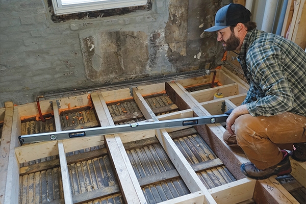
It is not uncommon for a building more than 100 years old to have floors that are out of level, but to have those floors be out of level more than 2 inches is a challenge to fix. In this particular three-story, three-unit building, the load-bearing center beam had dropped, while the brick exterior perimeter walls had remained in place. The resulting 2-inch-plus drop is evident in all three of the stacked units, each owned separately.
Attempting to jack the center beam in a building this old would likely cause severe and unpredictable consequences. The most benign of these would be that interior doors might not operate and plaster would crack; the worst-case scenario would be brick-wall failure and plumbing breaks. At the same time, there is no guarantee that 100 years of sagging could ever be corrected by jacking.
So we had a 2-inch drop down the center of the building. This might be interesting character in living rooms and bedrooms, but in kitchens and baths, it’s a big problem. Tubs, vanities, and toilets need to be placed on a level surface. Imagine what your tub would look like with a 1 1/2-inch taper from left to right. Or envision a furniture-style vanity with more than an inch cut off one side of its legs. People certainly do it, but that doesn’t make it right.
In this bathroom remodel project, the floor dropped roughly 2 1/2 inches in 8 feet. To level from the highest point (the exterior wall) would leave an approximate 2 1/2-inch step up at the bathroom door threshold. Sure, this would yield a level floor, but a step that large would create an obvious and unacceptable tripping hazard. Instead, we chose to remove material from the uphill side of the existing joists.
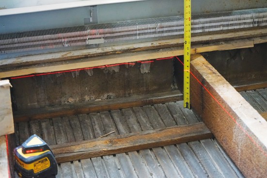
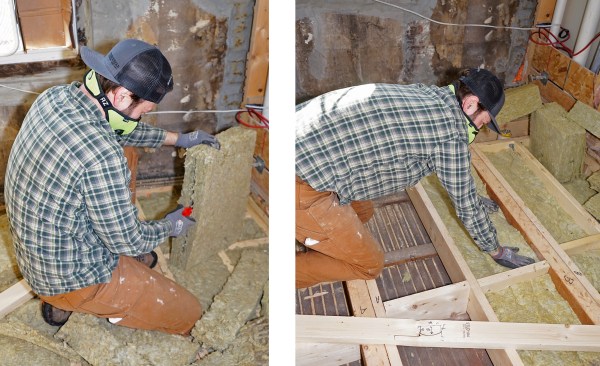
After removing the existing flooring, a level laser line shows 2 inches of wood to be removed at the high end of the 3×8 hemlock joists (above).
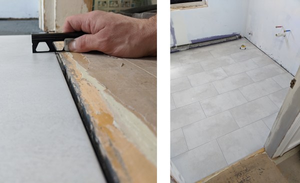
Here, Hovious snaps a cut line along the laser line (above left), then screws a ledger guide to the joist (above right).
Doing this requires increasing the load capacity of the remaining framing. In our case, we sistered additional support to the existing joists and added new framing between them. Because the renovated bath would have electric radiant heat, extra material was removed to account for the added finish-floor height.
Original Structure
The original floor joists were full-dimension 3×8 hemlock. The joists were spaced roughly 32 inches on-center (some were spaced about 31 inches, some about 33 inches). Instead of being supported by wood framing such as a rim or band joist, the floor joists were installed directly into the inner wythe of the exterior brick wall and locked into place with mortar. The joists spanned the entire 20-foot width of the building, supported by one load-bearing center wall.
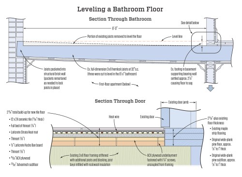
By ripping the joists back instead of packing them up, the authors were able to bring the bathroom’s final floor system flush with the existing floor in the adjoining living room. The final buildup, including two layers of subfloor, a layer of Laticrete Hydro Ban board, Laticrete Strata heat mat, thinset mortar, and ceramic tile, came to 2 3/4 inches.
The existing subfloor was 7/8-inch-thick random-width plank flooring, presumably originally 1 inch thick, run perpendicular to the floor joists. The flooring was random-width wide-plank softwood (probably hemlock), also run perpendicular to the joists. Everything was installed with hand-cut nails.
Deflection. At a rough calculation, the original framing had a deflection rating of about L/600—surprisingly stiff. Technically, this would qualify the floor to support ceramic tile, when installed properly. (Natural stone requires L/720 or better, while ceramic tile requires only L/360).
However, just walking on the floor was enough to deter us from installing tile with anything but a taillight warranty: There was significant bounce and movement between the joists. But when we were done ripping down and sistering the joists and reinforcing the floor system with additional joists, its deflection penciled out at roughly L/1000—stiff enough for us to feel comfortable.
Cutting Down
Because the joists were so far out of level, we decided to remove material at the high side and taper down to zero inches, creating a level and flat base to build from. Using a laser level and various beam levels, we found the lowest common point and marked that as zero inches. From there we found level at the far end of each joist, marked and snapped lines, and used jointed lumber as a straightedge and ledger. The ledger was temporarily screwed to the existing joist. We cut as deep as possible with a circular saw, running along the ledger. We finished the cuts with a recip saw, then used a belt sander to fine-tune the cuts.
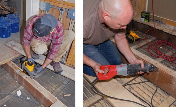
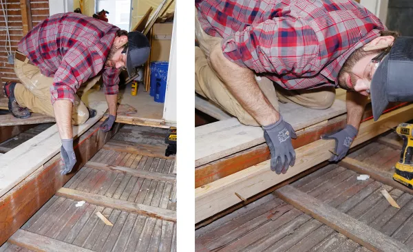
Hovious rips the joist level with a long angle cut using a circular saw, though the circular-saw blade did not cut all the way through the 3-inch joist (above left). Co-author Warren O’Shea finishes the cut with a recip saw (above right).
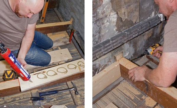
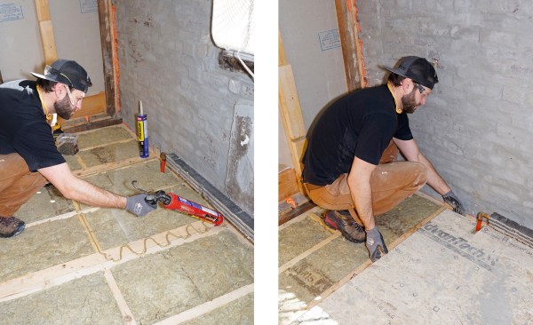
O’Shea applies construction adhesive to a ledger header (above left) and screws the header to the existing joist (above right).
Rebuilding
Regardless of finish, our typical buildup beneath tile involves minimum 2×8 floor joists, two layers of plywood totaling 1 1/4 inches, and an uncoupling membrane. Cutting down the joists gave us enough room for this typical tile buildup, as well as in-floor electric radiant heat. The finished-floor height at the doorway over the center wall was 2 1/2-plus inches above the joists. Total buildup will be around 2 3/4 inches (see illustration, previous page).
After cutting down the joists, we remortared the original joists into the brick wall, and then sistered them with 2x8s ripped down to the same taper. We installed blocking and framing to bring our joist spacing to 16 inches on-center or less, screwing headers between the original joists to catch new mid-span joists (for good measure, we glued the headers to the original brick). We added new joists under existing walls for support. We screwed and glued all framing with GRK framing screws, 3 1/8 inches or 2 1/2 inches, and PL Premium urethane construction adhesive and used joist hangers where possible. We added blocking at roughly 32 inches on-center to stiffen the floor and create a unified system. See lead photo on previous page.
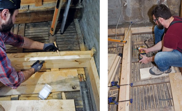
Hovious scribes a 2×8 sister along the existing joist (above left). Carpenter Mike Raulston attaches the sister (above right).
To improve the efficacy of the in-floor heating, we insulated the voids with R23 and R15 Rockwool insulation. We should achieve roughly R35 below the floor system. (In some places, we had to peel the R15 in half because of the ripped-down joists.) We then installed AdvanTech 3/4-inch subflooring, again using PL Premium urethane construction adhesive and 2 1/2-inch GRK framing screws.
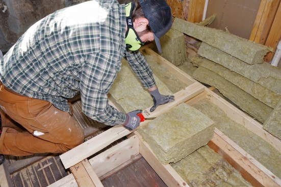
Hovious cuts Rockwool insulation to fit a cavity (above)…
… then splits the batt insulation as needed for thickness (above left). He installs the Rockwool into a joist bay—the joist bays varied in depth (above right).
Subfloor adhesive is applied to a reinforced joist (above left). The AdvanTech subfloor is then slid into place (above right).
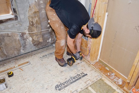
The subfloor is fastened down to the floor framing with 2 1/2-inch GRK screws (above).
Next, using shorter, 1 1/4-inch screws, we applied 1/2-inch ACX plywood as underlayment over the 3/4-inch subfloor, running the opposite direction. (We did this to provide a layer of uncoupling from the joists. Uncoupling helps to minimize framing movement telegraphing through to the tile and potentially causing failures.)
All plywood was screwed 6 inches on-center in the field and 3 inches on-center around the perimeter. Once both layers of plywood were finished, new walls were framed in as necessary.
Next Steps
When the plumbing and electrical rough-in was complete, we moved on to the finish process: first setting the tub, then installing drywall and backerboard, and then finally installing the tile buildup. We first thinset and screwed Laticrete Hydro Ban board to the ACX as a thermal break. Then we embedded the heat mat in thinset mortar. After that, we installed the heat wire and skim-coated with thinset. Finally, once all of that was dry, we installed the tile.
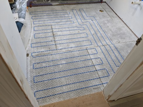
The Laticrete Strata Heat mat is thinset to Laticrete Hydro Ban board, the Hydro Ban acts as a thermal break. Heat wire is laid out serpentine-style on the mat’s pegs per the manufacturer’s recommendations (above).
The tile is set in a full bed of thinset using a 1/2 x 1/2" Euro-notch trowel to a 1/4-inch thickness. The thinset is applied slightly thinner at the door to flush the new tile up with the existing floor (above left). The rest of the 12- by 24-inch tile floor is installed level to first row using leveling clips (above right).
Photos by Ted Cushman and Chris Hovious; illustration by Tim Healey


