
Have you ever looked over an engineer’s structural calculations and felt like they were written in a foreign language? The purpose of this article is to try to make a little sense of the terms and symbols engineers use.
Moment
This is a way of describing a force acting at a distance. A teeter-totter is a good example (see Figure 1). Let’s assume that the seats are 14 feet apart and the hinge point is fixed at the middle of the board, 7 feet from each seat. You (the 160-pound adult) put your child (40 pounds) on the seat that is resting in the gravel, then walk to the other end to get on.
Will the teeter-totter balance? The moment at the child’s end is only 280 ft.-lb. (40 lb. x 7 ft.); the moment at your end is 1,120 ft.-lb. (160 lb. x 7 ft.) No, unless you use your legs, your duff is on the ground. The units are expressed as force times distance, giving foot-pounds of moment. When moments are stated, they are typically accompanied by a reference point — a location from which the distance to the acting force is measured. So where would you have to sit on the plank if the teeter-totter is to balance? The equation looks like this:
40 lb. x 7 ft. = 160 lb. x ? ft.
280 ft.-lb. ÷ 160 lb. = 1.75 ft.
The calculation of moments is basic to the engineering process; it is required for members, walls, foundations, and even entire buildings.
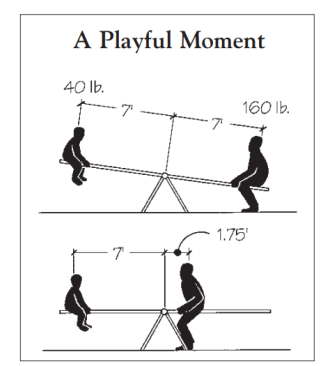
A moment is a force acting at a distance. In the example of the teeter-totter, the weight of the child acts at a 7-foot distance to produce a moment of 280 foot-pounds. To balance, the adult must sit at a distance of 1.75 feet from the pivot point.
Reaction
This is a fancy way of referring to the amount of weight an element contributes to a particular location. The reaction of a beam on a wall is the amount of load the beam delivers to the wall. If you see a notation like “Rmax” this is shorthand for the maximum reaction.
Shear
This is a type of force that wants to make adjacent materials move past each other (see image below). This includes: The movement of adjacent wood fibers within a member in a direction parallel with or perpendicular to the grain The movement of two individual members with respect to their original positions The movement of materials with respect to fasteners such as nails, screws, or bolts.
When you see the phrase lateral load, this refers to shear forces acting in a direction parallel with the ground surface. The causes of these lateral loads can be wind, retained soil, water, earthquake, or impact by an object. Stability of a structure is achieved only when lateral loads are properly distributed through the structure, into the foundation, and out into the surrounding soils.
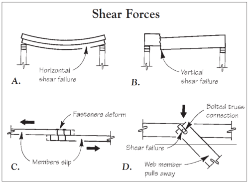
Shear force causes adjacent materials to want to slide or slip past one another. In a wood member, horizontal shear (A) acts parallel to the wood grain, while vertical shear (B) acts across the grain. The movement of a member with respect to a fastener may also be the result of shear force (C). Shear also describes the movement of two members with respect to their original positions, as in the example of a bolted truss web member pulling away from the top chord (D).
Modulus of Elasticity
Modulus of elasticity (MOE) is one of the basic properties of all materials. It’s determined by experiment using very sensitive equipment. A measured length of wood is placed in a machine that attempts to stretch it by pulling from each end. A record is made of the elongation of the wood for everincreasing loads. Given sufficient data, a straight-line relationship between load and elongation can be demonstrated for any load below that which would cause wood fiber damage. The slope of this line is the MOE. Once it is calculated, we can predict the deformation of this material under any given load within the tested limits.
The greater the MOE, the greater the force required to stretch a given length of that material. The following is a list of common materials and their respective MOEs:
Steel 29,000,000 psi
Cast iron 13,500,000 psi
Aluminum alloy 9,900,000 psi
Douglas fir 1,700,000 psi
For those of you who might be interested, the formula for calculating deformation is:
deformation = P x L / A x E
where P is the load in pounds, A is the cross-sectional area of the member in square inches, L is the length of the member in inches and E is the modulus of elasticity.
Fiber Stress: Fb, Fc, Ft, Fv
Fiber stresses refer to the demonstrated ability of wood to resist forces applied in specific directions with respect to the grain of the wood. Building codes contain long lists of these allowable stresses for various wood species. The smaller letters are used to highlight the force directions under consideration:
b is for the tension component of bending forces
c is for compression forces acting on the ends of the member (like columns or posts)
t is for tension forces pulling on each end of the member
v is for resistance to shearing forces (also called horizontal shear, but not abbreviated Fh)
Section Properties: Area, Section Modulus & Moment of Inertia
Given the forces on a member and the allowable fiber stresses of the material being used, you can determine the minimum acceptable section properties of that member. There are three to be considered: The area of the member, the section modulus (or simply the section) and the moment of inertia (or simply the inertia).
Small letters are used when referring to calculated minimums versus actual amounts provided. For example, r indicates the minimum required amount and f is the actual amount furnished. In your engineer’s calculations, you may see some notation like Sf > Sr, ok. This is just a check that shows that the selected member meets the design criteria. The furnished amount should always exceed the required amount.
Area (Ar, Af). The area of any wood member can be calculated by measuring the width and depth at the cut end and calculating that area in square inches. The amount of area furnished establishes an upper limit on the reaction a member is permitted to deliver to its support. This maximum can be expressed as
Rmax = 2 x Af x F / 3
Section (Sr, Sf ). The section of a member limits the strength of the member when subjected to bending moments. For a solid wood beam with a depth less than 12 inches, the section it furnishes can be determined by the following formula:
Sf = width x depth x depth / 6
The result will look a little funny at first because the units will be inches cubed. The required section for any member is determined using the calculated moments and the allowable fiber stresses. The expression is written as:
Sr = moment / fiber stress
If the moment is expressed in inchpounds and the fiber stress is expressed in pounds per square inch, the pounds cancel and you are left with inches cubed. All the math aside, the important word to remember with regard to section is the word “strength.” The larger the section, the stronger the member.
Inertia (Ir, If ). The inertia of a member when used with the modulus of elasticity of the particular material allows us to predict the deformation (deflection) of that member when loaded. The inertia of a solid wood beam can be determined by the following formula:
If = width x depth x depth x depth / 12
in inches to the fourth power!
There are all sorts of complicated formulas for determining deflection under various loading conditions, but these are mainly of use to engineers designing structural members. What you should remember is that the larger the inertia furnished (If), the smaller the resulting deflection. Or, more simply, inertia is directly proportional to stiffness.
Kip
In the English system, we use pounds to describe weight and feet or inches to describe distance. You know that 2,000 pounds is called a ton, but did you know that 1,000 pounds is called a kip? (It’s a shortened form of “kilo-pound”.) So, when you see a notation like kpf, think kips per foot. For example, 0.48 kpf would be equal to 480 pounds per foot. Engineers use kips because it makes the numbers much easier to work with (especially with a slide rule) and reduces errors caused by lost zeros.


