When I’m reviewing the prints for a remodeling job, one of the first items I check for is the addition of new structural beams, which always require plenty of manpower and extra work. But prints don’t always give you a clear picture of actual site conditions.
Such was the case with a split-level home we recently remodeled. To increase room size on the ground floor, the plans called for the removal of a bearing wall, which would be replaced with a 15-foot-long beam made from a pair of 1 3/4-inch-by-14-inch Microllam LVL joists. The problem was that setting this 14-inch-deep beam flush to the top of 2×8 floor joists would leave nearly 7 inches of Microllam hanging down into the room. Not very attractive, in my book.
Because the split-level had a ceiling height of only 7 feet 4 inches on the first floor, it wasn’t difficult to convince the homeowner that installing a shallower 7-inch-high beam would be a better solution. Admittedly, our approach was more expensive than cutting a pair of stock LVLs to size, as shown in the original plan; but a beam designed to be installed flush with the finished ceiling would result in an unobstructed ceiling and make the room much more attractive.
A Better Beam?
Typically, a shallow 7-inch wood beam requires reinforcing with a steel plate or I-beam to give it enough strength to span 15 feet. In the past, I’ve always hired an engineer to design these wood-and-steel “flitch beams,” then ordered the steel from a local fabricator and assembled them on site.
But the installation of large beams — which involves lugging around 350-pound plates and assembling them on a table, then hoisting a 600- or 700-pound beam overhead — is a daunting task with a small crew. At my age, I wasn’t looking forward to the process.
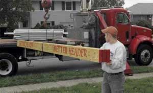
Convinced there had to be a better way, I decided to try a prefabricated beam from the Better Header Co. (631/242-1975, www.betterheader.com). I had seen this company’s product at a trade show and promised myself that the next time I had to install a steel flitch beam, I’d give it a try. I wanted to see if the system was any better than my site-built approach.
To get a beam design that would work in my situation, I provided the company with the length of the span, the width of the structure above, and an estimate of all of the loads that the beam would have to carry. (Sales are typically handled through your local lumberyard.) I also provided a sketch of the existing structure’s cross section that showed the span of the floor above, the location of a second-floor bearing wall, and the ceiling above.
The price for a delivered beam was $1,100. At first, that seemed expensive, especially since I could purchase all the components for around $850. But when I considered the additional $200 for the engineering fee, and the two hours or more we’d have to spend assembling and lugging around the beam with four men, I decided that the prefabricated beam was the better deal.
I was promised delivery to the job site within a week. But one problem remained: This beam would be heavy. Built of three 13/4-inch-by-7-inch LVLs reinforced with two 1-inch-by-7-inch steel plates, all bolted together, the beam would weigh nearly 800 pounds.
I needed to make sure that I was prepared to handle the load when the beam arrived.
Supporting the Floor System
Delivery was scheduled for noon by boom truck. That gave us an entire morning to prepare the site for installation. The homeowner had already gutted the room, and a plumber had relocated some pipes the day before. We had to work around a few wires, but most would be relocated later by an electrician.
To support the ceiling joists while we installed the beam, we needed to build a pair of temporary 2×4 walls. In general, temporary shoring should be built as close to the original beam as possible. In this case, placing the temporary 2×4 walls 2 feet on either side of the existing bearing wall’s centerline would leave us with the 4-foot working area we’d need to accommodate our jacks.
With only a floor load and attic above to support, I felt that this 4-foot clear span wouldn’t be a problem. But in more complicated cases where there is a posted ridge or other substantial load above, I always consult an engineer, who specs out distances, connectors, and the proper removal sequence.
After measuring, cutting, and laying out the plates for both temporary walls, we went ahead and installed the first one. (The other would have to wait until we had the beam positioned.) We began by fastening our top plates to the floor joists above, then positioned the floor plates directly below and placed one stud under each joist. To ensure a snug fit, we measured for each stud and then cut long by about 1/8 to 1/4 inch. If a stud still seemed loose, we ran a hardwood shim under the bottom plate and beat it in.
We held everything together with 3-inch-long #10 deck screws — two to three per stud connection — which would make it easy to take everything apart afterward and reuse the materials for other parts of the project.
Before loading the studs by removing the bearing wall, we ran horizontal 2x4s to connect the studs at midheight. This kind of lateral bracing helps prevent individual studs from bowing. We also added a diagonal 2×4 brace at the end of each wall, fastened at the top, middle, and bottom to help prevent bowing or racking.
In addition, prior to removing any bearing structure, it’s good practice to measure and write down the distance from the floor to the bottom of the existing joists in a number of places. I wrote these measurements right on the joists next to the beam, and used them later to determine whether the floor framing had dropped from its original position after the job was complete.
It’s also good practice to go upstairs and make written notes of any unevenness in the floor, cracks in plaster or drywall, or problems with door swings and clearances, and to point them out to the homeowner so you don’t end up owning existing problems. I also document these issues with a digital camera prior to any wall removal.
With the existing conditions documented and one temporary support wall installed and braced, we were ready to begin demolition. Since the joists above ran continuously over the bearing wall, we could remove the old bearing wall with only one support wall in place. More typically, the joists break over a center bearing wall, requiring two support walls prior to demolition.
As so often happens on the day of a big job, I was short one man, so installation of the big beam was up to just me and one helper. Fortunately, though, we were well-prepared. That morning, I had rented two Hi-Jacks (Vermette Machine Co., 800/348-6454, www.vermettlifts.com) from the local tool-rental store. These freestanding jacks are capable of lifting 500 pounds each up to a height of 10 feet (somewhat less in interior spaces, where structures overhead may interfere with the lifting mechanism), and are easily transported and assembled on site.
I had also placed two furniture dollies outside on the sidewalk, thinking we would have to drop the beam onto them and roll it up to the house. But when the boom operator opted to send the beam right through the front doorway instead, he got no argument from me.
After we transferred the beam onto both jacks, we rolled it into position. Then we assembled and braced the second temporary support wall for the other half of the room. With the second wall in place, we removed the last section of header from the old bearing wall.
Cutting in the Beam Pocket
Next, we marked the location of the new beam on the floor joists, centering it on the old bearing wall. The beam actually measured almost 7 1/2 inches wide, plus I added an extra 1/8 inch for wiggle room, so we marked a 7 5/8-inch-wide channel to receive the beam.
To get clean, straight cuts, we started our kerfs with a circular saw and finished up with a reciprocating saw. Even though a cut line that wandered 1/4 to 1/2 inch wouldn’t be a big problem structurally, square cuts look more professional, and they help justify the invoice later on.
After cutting the pocket, we cleaned up stray nails to make room for the beam. We were careful to cut all metal flush with the recip saw so that the beam wouldn’t push up the subfloor or finish floor when it was installed. And to accommodate a few stray telephone wires, we cut out a short section of the 1×6 subfloor to leave a 3/4-inch-thick chase above the beam.
Installing the Beam
Once the pocket was prepped, we proceeded to jack up the beam. The Hi-Jacks are stable and roll easily even when loaded, so the beam didn’t have to be perfectly aligned with the pocket when we started lifting.
Because of their design, though, the Hi-Jacks couldn’t lift the beam all the way up into the pocket. To hoist it the last 6 or so inches into place, we had to place cribbing between it and the lift. We did this by raising the beam as high as we could into the pocket (to keep it from rotating) and temporarily posting one end, which allowed us to lower the jack on that end and block under the beam with scrap 2-bys. After using the same approach to install cribbing under the other end, we were able to jack the beam fully in place, lined up flush with the ceiling joists.
One common problem with site-built beams is bolt heads sticking out just where a joist is sitting. But this header’s recessed bolts made it much less difficult to slide into position. Also, the rollers on the jacks made it easy to position the heavy beam precisely, even with the beam held up high.
With the beam in place, we installed tripled 2×6 posts below each end of the beam to lock it into position, and then lowered and disassembled the jacks.
To complete the installation, we fastened metal joist hangers to all of the floor joists; using a Paslode Positive Placement pneumatic nailer (800/222-6990, www.paslode.com) made the job go a lot faster.
In cases where the bottom of the joist sat flush to the bottom of the beam, we notched the end of the joist to allow the hanger to sit flush, too. Once again, the recessed header bolts made installing the hangers much easier, because they didn’t interfere with the hangers.
By rechecking the joist-height measurements I’d taken before removing the old bearing wall, I could easily find out how close the joists were to their original position. In this case, the floor wasn’t level to begin with, while the beam was laser straight. Where joists were too low, I drove hardwood shims between the plate and the bottom of the joist to raise the joist until it was flush with the bottom of the beam; then I installed the joist hanger.
Meanwhile, on the other end of the beam, the tops of some of the joists were as much as 3/8 inch above the top of the beam. Since my measurements for the finished floor confirmed that nothing had moved, it was apparent that the sagging of the original structure prevented the beam from going completely flush with the existing framing.
Because the section above included a tile floor, I chose to leave the joists as they were and deal with shimming drywall rather than try to straighten out the sag and risk cracking the existing tile floor.
Once all the hangers were in place, we removed the temporary walls. The entire job took approximately 4.5 hours and required two men. We paid $140 to rent the pair of Hi-Jacks for the day, which was much less expensive than paying four borrowed carpenters for 2 hours. And the jacks don’t break for lunch.
Mike Sloggatt is a remodeling contractor in Levittown, N.Y.


