During the last several years, wood science researchers at Virginia Tech have scrutinized the structural connections commonly found in residential wood decks. This work resulted in the publication of the Manual for the Inspection of Residential Wood Decks and Balconies (Forest Products Society, Madison, Wis.) and the JLC article “Load-Tested Deck Ledger Connections” (3/04).
For this article we turned our attention to residential deck railings — the guardrails intended to prevent people from accidentally falling off the edge. When decks rise more than a couple of feet off the ground, such accidents can be serious and even deadly, as news reports have corroborated. With many decks standing 8 feet or higher above grade, this is not an issue a builder can afford to ignore.
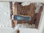
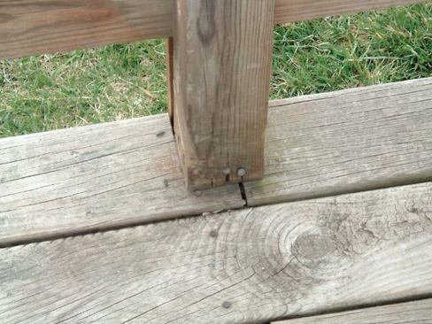
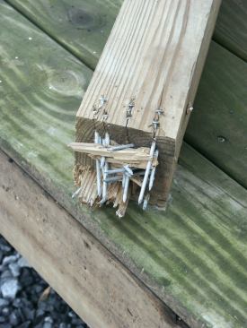
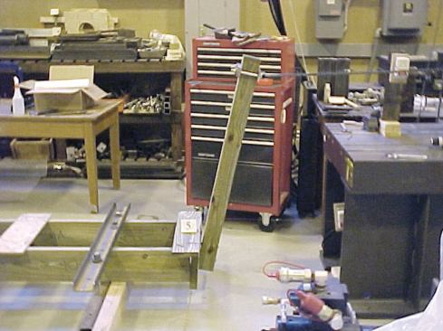
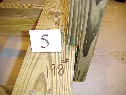
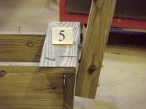
Researchers at Virginia Tech applied measured loads to deck posts to see which connections could meet code. The tests were spawned in part by one author’s observations of dangerously weak details on existing decks, as in the two examples below, where railing posts were simply toenailed into the decking. The post in the bottom photo was covered by a decorative plastic cover, which concealed the flimsy connection.
The point was brought home to us when Frank was asked to inspect the railing on a friend’s deck and found the rail posts toenailed into the decking, an unacceptably flimsy connection. Looking around our area of Virginia, we spotted other railing connections that made it clear that some deck builders, at least, aren’t aware of code requirements for deck railings.
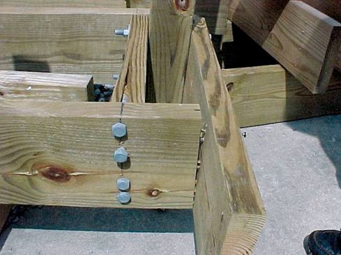
The authors first tested two post connections found commonly in their area, one where the 4×4 pressure-treated post is notched and lag-screwed to the band joist, and a second where the post is through-bolted to the deck band joist. Code requires that a rail post be able to withstand a 200-pound force applied in any direction. The researchers tested the worse-case scenario only, by pulling outward at the top of the post; they applied a 2.5-times safety factor, according to code-accepted test protocol.

Where common connection details fail to meet code loads, prefab …
What Code Says
The 2003 International Residential Code (IRC Table R301.5) specifies a minimum concentrated live load of 200 pounds for both guardrails and handrails. Footnote “d” defines the application of the 200-pound load as “a single concentrated load applied in any direction at any point along the top.” Judging by what we were observing in the field, it seemed obvious that many deck railings would not pass this loading requirement.
A guardrail is really a system of components connected together and fastened to the deck, including posts, railings, and pickets (or balusters). Rather than look at the entire guardrail system, we decided to narrow our testing to post connections. There are many ways to attach deck posts, so for practical reasons we decided to limit the possibilities to methods frequently used by carpenters in our geographic area.
What’s being built. By far the most common details we found locally were the cases shown in Figure 1, where the post attaches to a “band joist” at the outer edge of the deck structure. These posts are typically notched, but not always, so we decided to test the connections both ways.
Why Not Notch? | |
Cracks will typically develop from the corner of a notch (photo, right). As a crack develops, a steep “slope of grain” can critically reduce the section of the post, as the drawing shows. Several of the 4×4 posts we tested were notched around the band joist — a common detail in the field. While you might expect the notch to be the weak point in the connection, in fact none of the test posts failed at the notch. Even so, notching should be avoided, because it does substantially reduce the strength of the post. Here’s why: Many years of observation have proved that moisture cycles will typically cause cracks to develop and propagate, parallel to the grain, from the corner of the notch. This may not be apparent when the post is first installed, but it happens gradually over time.According to the grading rules for lumber, a piece of 4×4 No. 2 southern pine can have a “slope of grain” of up to 1:8 (or 1 inch in 8 inches). If a 4×4 with a slope of grain of 1:8 is notched 1.75 inches deep, a crack propagated along the grain will reduce the 1.75-inch-thick section at the notch to only 3/4 inch at 8 inches above the corner of the notch — not something you’d want to bet your life on. | |
While many of the post connections we observed were obviously loose and allowed us to shake the railing, some of the posts seemed strong. But the question we wanted to answer was whether these connections would stand up to a code-protocol test load.
Setting Up the Test
A load “applied in any direction” includes people leaning against the railing or sitting on top of it. But it also means that the railing should be able to resist a load applied from the outside — for instance, a tree that falls against it. We decided to limit our testing to the worst-case scenario — that of a 200-pound load applied from the deck side perpendicular to the very top of the post. Making a connection to resist this force at the base of the post is harder than you might think, because of the lever-arm effect (force x distance): The magnification of this 200-pound horizontal force produces a couple of thousand pounds of load at the base of the post (see “Forces in a Typical Guardrail Post,”).
| | |
Moment = force x distance Applied moment = resisting moment Applied moment = 200 lb. x 44.75 in . = 8,950 inch-pounds at base of post Resisting moment = ? lb. x 5.25 in. (5.25 in. is the distance from bottom of joist to bolt centerline) Resisting force = 8,950 inch-pounds / 5.25 in. = 1,705 lb. | A guardrail post can behave like a lever: The force applied at the top gets multiplied by the length of the post — the lever arm — to produce a large moment, expressed in inch-pounds, at the base. The resisting force at the base, here represented by a single bolt, is also multiplied, but by a much shorter lever arm — 5 1/4 inches in this example. In the case shown here, representing a typical residential deck rail post 36 inches high, the bolt would have to provide nearly 2,000 pounds of resisting force. While the steel itself might be up to the task, the wood fibers under the washers would not be strong enough, as the authors’ tests indicated. |
We assumed that the top of the railing was 36 inches above the deck surface (the minimum height allowed by the IRC) and that the deck boards in an actual application are at most 1.5 inches thick. Thus, the horizontal test load was applied to the post 37.5 inches above the top of the simulated deck joists.
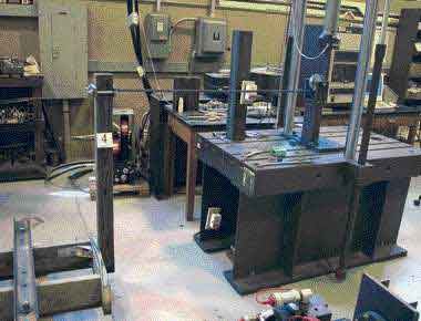
Our test machine applied a measured force, using a roller chain and pulley to redirect its vertical motion to a horizontal force at the top of the post. The post was attached to a simulated deck framing system that included two joists and a band joist with the post attached to the band joist with bolts or lag screws, just as in a real deck. We secured the deck joists to the concrete floor of the lab, and attached a transducer to the joist near the post location to verify that the test assembly didn’t move. We also attached a transducer to the post 37.5 inches above the joist to measure how much it deflected during the test.
Safety factor. The code requirement says that the post must be able to withstand a 200-pound load. But when a structural assembly is tested in a lab, the load gets multiplied by an appropriate safety factor, which is intended to allow for the uncertainties of field installation and the fact that the connections may degrade in service from repeated loading and weathering (but not rot).
We used a safety factor of 2.5, a number that has been in the model codes for decades for testing structural assemblies. So, for our testing, we needed to apply a 500-pound load to determine whether the post connection could be considered “code-conforming.”