In some European countries, hydronic heat pump sales have exceeded boiler sales for several years running. The North American market is not there yet, but many signs point to a promising future, especially for air-to-water heat pumps.
This trend is reshaping the hydronic heating and cooling markets in significant ways. It’s creating unrivaled opportunities compared with previous advancements in hydronics technology. One example is adding cooling to a hydronic heating offering. That in itself is a really big deal! It provides an answer for clients who want hydronic heating but ask the inevitable question: “What should I do about cooling?” It also appeals to those who are highly motivated to reduce carbon emissions but still want a system that provides superior comfort—something that properly installed hydronic heating systems have a track record of delivering.
Heat Pump Helper
It is estimated that there are more than 6 million hydronic heating systems currently installed in the U.S. The vast majority use boilers operating on fossil fuels as their heat source. This established base sets the stage for how air-to-water heat pumps will initially gain market share. Many will be integrated into existing boiler-based systems.
Note that I did not say that most air-to-water heat pumps will replace existing boilers.
While it’s true that clients wanting to eliminate fossil fuels from their heating system can have their existing boiler removed as part of an air-to-water heat pump installation, it’s also true that retaining an existing boiler that has remaining service life offers several benefits.
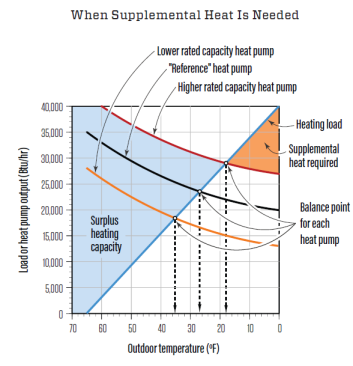
The heating load of any building increases as the outdoor temperature drops. Unfortunately, the heat output of any air-source heat pump decreases as the outdoor temperature drops. This effect is illustrated in the chart above. The heating-load line crosses the heat pump’s heating-capacity line at a “balance point.” This is where the building’s heat loss is the same as the heat pump’s output. At warmer outdoor temperatures, the heat pump has more than sufficient capacity to heat the building. At outdoor temperatures below the balance point, some type of supplemental heat input is needed to maintain the desired comfort temperature in the building. This is where that existing boiler comes in. It can operate along with the heat pump to ensure sufficient heat delivery to the building.
Assuming that the boiler is sized to the building’s design heating load—and most are significantly oversized—it can provide 100% backup heat if the heat pump is down for service.
Another benefit is that most gas- or oil-fired boilers used in residential and light commercial buildings have low electrical power demands compared with a heat pump or electric resistance heating elements. This allows a small portable generator to keep the boiler and a few circulators or zone valves operating during a prolonged power outage. The system can be easily wired to allow the owner to switch between utility and generator power.
Using the existing fossil fuel boiler as the supplemental and backup heat source might also eliminate the need for an electrical service upgrade, which can be necessary, especially in older homes, if any form of electric resistance heating were used for these purposes.
When the Price Is Right
The rapid shift toward electrification in the HVAC market as well as the growing electric vehicle market continues to strain existing utility grids, especially during periods of peak demand.
Time-of-use electrical rates are one demand-side management tool used by utilities to encourage electrical usage during low-demand periods and discourage use during high-demand periods. The concept is simple: Price electricity low during periods of low demand and significantly higher during periods of high demand.
The chart below shows an example of such a rate structure. Depending on the time-of-use rate structure available, it might make sense to use the existing boiler for heat needed during peak periods. Likewise, operating the heat pump during off-peak periods ensures the lowest price for electrically sourced heat.
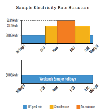
Shown here is an example of time-of-use rate structure offered by a utility company. At these rates, it would make sense to use the existing (fossil-fuel) boiler from noon to 6 pm (and possibly during shoulder-rate times depending on the difference between these rates and the price of gas or oil), and use the heat pump during off-peak periods.
I’ve worked on research projects based on this concept, and the results to date have been encouraging. An air-to-water heat pump combined with thermal storage has been able to maintain stable comfort in a home in a cold northern climate while operating only during off-peak hours. The combination of air-to-water heat pumps and thermal storage will likely see wider implementation in the future, especially when heat pumps operating on R-290 refrigerant, which allows discharge water temperatures up to about 170°F, become available in North America.
Air-to-water heat pumps can also be combined with water-based thermal storage to leverage the lower off-peak electrical rates.
Making Connections
The piping diagram shown below can be used for a “conventional” boiler. This classification includes cast-iron, steel-fire-tube, and copper-water-tube boilers. These boilers are not intended to operate at low water temperatures that allow sustained condensation of flue gases produced during combustion. If allowed to form, the acidic condensate can eat through a typical 26-gauge-galvanized vent connector pipe in a matter of months. The photo below shows a vent connector that’s only 6 months old and has failed due to corrosion from sustained flue gas condensation.
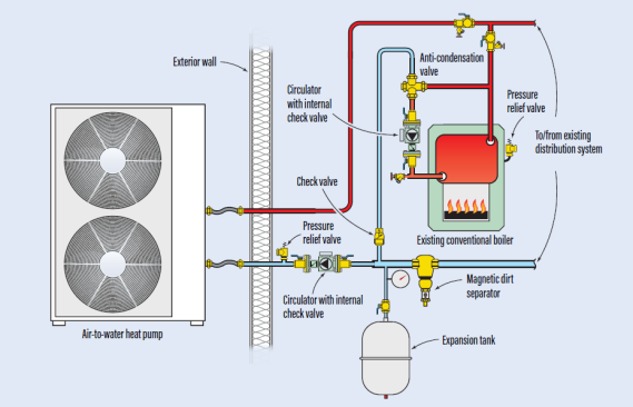
This diagram shows a parallel-piping system that can be used for a “conventional” boiler. To prevent sustained condensation of flue gases during combustion, the system includes an “anti-condensation” thermostatic mixing valve piped in near the boiler.
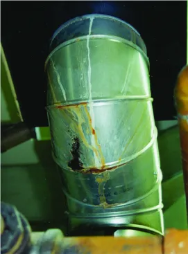
This vent connector had been installed only months before sustained flue-gas condensation caused this corrosion.
The general concept that applies to situations where multiple hydronic heat sources are used is to connect them in parallel not in series. This allows any heat source to be the sole heat provider. It also allows simultaneous operation if and when necessary. It prevents needless heat loss that occurs when heated fluid flows through inactive heat sources. Finally, it allows any of the heat sources to be serviced or even temporarily removed if necessary, without curtailing operation of the remaining heat sources.
Anti-condensation valve. The common way to prevent sustained flue gas condensation is to install an “anti-condensation” thermostatic mixing valve in the near boiler piping. An anti-condensation valve mixes higher temperature water leaving the boiler with cooler water returning from the heat emitters so that the water entering the boiler is nominally 130°F or higher, which prevents sustained flue gas condensation. It’s an important detail that helps prolong the life of a conventional boiler and its venting system.
The piping diagram below shows a “mod/con” boiler, which is designed to operate with sustained flue gas condensation and, as such, doesn’t require an anti-condensation mixing valve.
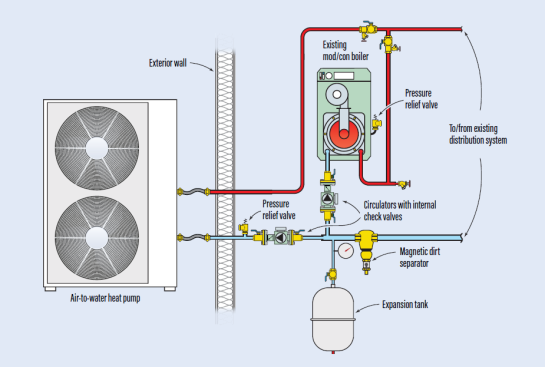
This diagram shows a parallel-piping system that can be used for a “mod/con” boiler, which is designed to operate with sustained flue gas condensation and, as such, doesn’t require an anti-condensation mixing valve.
Circulator with internal check valve. In each diagram, the boiler and heat pump have an associated circulator equipped with an internal check valve. The heat pump circulator operates only when the heat pump is active. The boiler circulator operates only when the boiler is active. The check valves prevent flow reversal through an inactive heat source when the other heat source is operating.
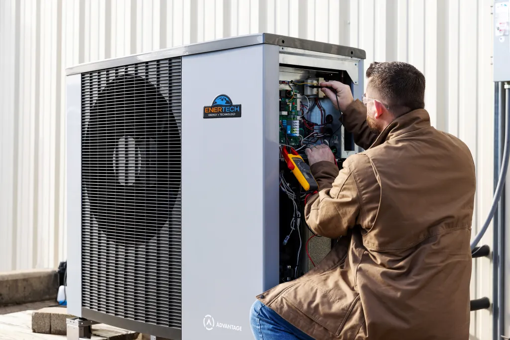
Magnetic dirt separator. All the parallel-piping diagrams in this article show a magnetic dirt separator. It captures dirt or other debris in the system, and its strong internal magnet captures iron oxide particles. The latter are typically present in existing hydronic systems that have cast-iron or steel components. If not captured and periodically drained from the system, these particles can accumulate on the heat transfer surfaces inside the heat pump. The resulting “fouling” will reduce the heat pump’s heating capacity and efficiency. Iron oxide can also collect within the rotor can of ECM circulators. I strongly recommend installing a magnetic dirt separator as part of the “surgery” undertaken when adding the heat pump.
The Brains
There are several ways to control a heat pump and boiler in the same system. The most common is to treat the heat pump as the primary heat source, favoring its operation over the boiler whenever it can maintain comfort in the building. The boiler would operate only as a supplemental, or backup, heat source if and when the heat pump’s output is inadequate.
This type of control is easily handled by a two-stage boiler controller. The controller’s first stage contacts turn on the heat pump and its associated circulator whenever the system needs heat. The controller monitors the temperature change that occurs with the heat pump operating. If it “judges” that the required water temperature will not be met by the heat pump after a few minutes of operation, it closes another set of contacts, turning on the boiler and its circulator.
Staging controllers have adjustable settings for water temperature set points, differentials, inter-stage time delays, and other options. They are widely available from several sources.
Freeze Protection
Air-to-water heat pumps are available in “monobloc” and “DX split” configurations.
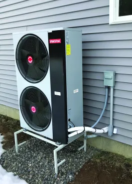
A monobloc heat pump is completely self-contained and installed outside. It’s factory-charged with refrigerant and requires only water piping and electrical connections.
Most manufacturers of monobloc heat pumps require the use of antifreeze in their units to provide freeze protection during potentially long power outages in subfreezing weather. A 30% solution of nontoxic propylene glycol is adequate in most areas of the U.S. Extremely cold locations may require 40% to 50% solutions.
Although it’s possible to configure systems with heat exchangers that separate the antifreeze solution in the heat pump from water in the remainder of the system, doing so reduces thermal performance and can add significant expense. The more common approach is to fill the entire system with the antifreeze solution and sell the owner on the benefit of equipping the system to survive a long-term winter power outage.
DX-split systems. Air-to-water heat pumps designed as “DX split” configurations (see photos and illustration below) have outdoor and indoor modules connected by a copper refrigerant line set. One benefit of these units is that there is no water outside and thus antifreeze is not required. One constraint is that basic refrigerant skills and tooling are required to commission the system. Installers need to make proper flare connections, pressure test and evacuate the line set, and open the service valves in the outdoor unit to release the refrigerant into the line set. They may also have to add refrigerant if the line set is longer than the allowance set by the manufacturer.
Shown above is an example of the outdoor unit for a DX split air-to-water heat pump.
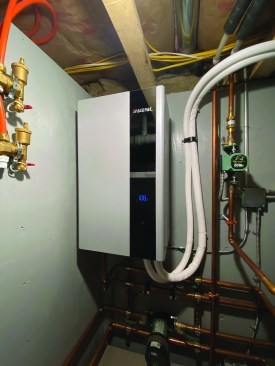
Copper refrigerant tubing, covered with white insulation, connects the outdoor unit (left) to the indoor unit (above).
Click here to enlarge image below.
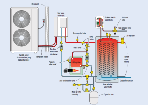
This parallel-piping diagram can be used for a "DX split" system. It uses a “reverse indirect” tank as both a buffer and domestic water heater. That tank can accept heat from the heat pump’s indoor unit or the existing boiler.
Expandability
Systems with air-to-water heat pumps can be configured to include domestic water heating. The illustration above shows a system that uses a “reverse indirect” tank as both a buffer and a domestic water heater. That tank can accept heat from the heat pump’s indoor unit or the existing boiler.
The heat pump or the boiler heats the water in the shell of this tank. Cold domestic water passes through multiple copper heat exchanger coils whenever hot water is drawn from a fixture.
The temperature of the domestic water leaving the tank coils depends on the temperature maintained in the tank shell. It also depends on the draw rate for domestic hot water. If the heat pump maintains the water in the tank shell at 5°F to 10°F above the expected domestic hot-water delivery temperature, and reasonable draw rates are sufficient, the tank can often fully heat the water as it passes through the coils. If these conditions are not present, the tank can still preheat the domestic water. That water then passes through some type of “booster” heater, such as an electric tankless unit, to bring it to the required delivery temperature. Be sure to check the thermal rating data of the reverse indirect tank to determine if a booster heater is needed.
Chilling Out
When someone buys an air-to-water heat pump for hydronic heating, they’re also buying a machine capable of producing chilled water for cooling.
Although there are systems where the heat pump provides only space heating and perhaps domestic water heating, the ability to add cooling opens up opportunities that were not in the residential or light-commercial hydronics “wheelhouse” in decades past.
If you compare the illustration below with the illustration for the split system (above), you’ll see overlap. The parallel arrangement of the heat pump and existing boiler remains, but instead of a DX split system heat pump, the second illustration shows a monobloc. This implies that the system will operate with a antifreeze solution. An air handler equipped with a cooling coil has been added to the system. The piping supplying chilled fluid from the heat pump passes through an electrically operated diverting valve on its way to the air handler. This valve allows the heat pump to switch between cooling and maintaining a suitable “hot” temperature in the reverse indirect for domestic hot-water production. Controls allow one of these loads to be prioritized over the other.
Click here to enlarge image below.
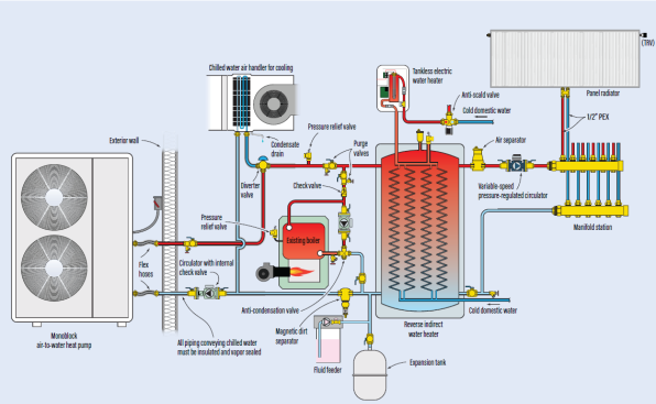
This parallel-piping diagram adds cooling to an existing monobloc boiler and (like the diagram for the split system) includes a reverse indirect tank that serves as both a buffer and a domestic water heater.
The air handler must be equipped with a condensate drip pan that connects to a suitable drain. During humid weather, several gallons of condensate can form each day. It is typically drained outside the building or, where codes allow, tied to the building’s DWV piping.
All piping conveying chilled water must be insulated and vapor sealed. I cannot overstress how important this is. The surfaces of the piping and components conveying chilled fluid at 45°F to 55°F are well below the dew point of surrounding air. If that air contacts these surfaces, condensate will form in a matter of minutes. Eventually, it will drip onto whatever is beneath it. You can probably imagine where this scenario will lead as far as callbacks and customer relationships are concerned.
I prefer elastomeric foam insulation such as Armaflex. It is readily available, comes pre-split to fit over pipes, and has strong, pressure-sensitive tape on its longitudinal seams to bond them together after the insulation is fit to the piping. All butt joints need to be bonded using a rubber-based contact cement. Elastomeric foam insulation also has low vapor permeability, eliminating the need for a separate vapor-barrier wrapping. This type of insulation can be easily and accurately cut using an electric carving knife. Unless codes require otherwise, 1/2-inch wall thickness is generally adequate to prevent condensation.
A big advantage of integrating a heat pump with a hydronic system is the option to add cooling with a chilled water unit on an air handler, as was done above.
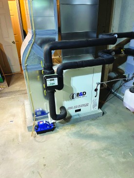
The piping for the air handler shown in the photo above is wrapped with elastomeric foam insulation. The circulator volute and isolation valves are wrapped with elastomeric foam tape, which is easier to fit to complicated surfaces. There was no floor drain in this installation, so a condensate pump was used to collect and eject the condensate outside the basement.
The reverse indirect tank in the illustration on the facing page serves as both a buffer and a domestic water heater. A very simple “home-run” heating distribution system, in which several panel radiators are connected to a manifold station, connects to the right side of the tank. Each radiator is equipped with a thermostatic radiator valve, allowing it to operate independently of the others. The variable-speed, pressure-regulated circulator automatically changes speed as the radiator valves open, close, or vary flow through their associated radiator.
What’s Ahead
Air-to-water heat pumps will have increasingly profound impacts on hydronic heating and cooling. They’re an ideal way to significantly “electrify” existing hydronic systems supplied by boilers and do so without foregoing the benefits of a “dual fuel” approach.


