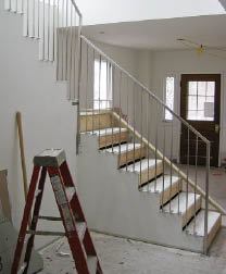
Sleek But Strong Handrail
I’ve mostly built traditional stairs using manufactured rail parts. Recently, though, an architect asked me to install a contemporary stainless steel handrail to fit a 10-by-10-foot opening. The L-shaped balustrade and the horizontal guardrail at the landing were to be fabricated from 1-inch square tubing, with 3/8-inch solid square balusters 4 inches on-center (1). Because the metal shop was several hours away from the job site, one of the first things I did was make an accurate full-scale template on sheets of plywood, fitting it to the rough stair carriage and providing actual dimensions. After getting approval from both the architect and the building inspector, I drove the plywood templates to the shop. Though this process took a couple of days, it was time well-spent; the actual installation went smoothly and took only about a day.
1
The architect wanted the fasteners for the balustrade to be concealed, but I was concerned about the rail being strong enough to pass inspection. The final design called for 1/4-inch-thick tabs welded at right angles to the end of each baluster, countersunk for structural screws so they could be fastened directly to the subtreads (2). Similar mounting brackets at the bottoms of the newels allowed for rock-solid attachment into the framing (3, 4). I used an angle grinder and utility knife to cut away the drywall and corner bead so I could screw the brackets directly to the stringers and headers (5).
2
3
4
5
Along the landing, I used a router to make mortises for the baluster brackets in the subfloor (6, 7). To ensure accuracy, I first clamped story poles to the top of each rail section and marked the baluster locations, then transferred the layout to the landing (8, 9). The mortises are 1/2 inch deep to accept the 1/4-inch tabs and create a 1/4-inch reveal between the finish floor nosing and the top of the drywall (10).
6
7
8
9
10
Before installing the walnut treads and landing nosing, I fitted notched 1/4-inch hardboard spacers around the baluster tabs, holding them 1/4 inch back from the edge to create the reveal between the drywall and treads (11, 12). Later, my drywall sub came back and patched all the bracket cutouts, leaving clean lines and invisible attachments (13, 14).
11
12
13
14
Keith Fitzpatrick is a remodeler in Barryville, N.Y.
Backyard Face-Lift
by Geoffrey Zimmerman
One result of the “new” economy has been that homeowners are staying put and fixing up the houses they already own, and so I’ve been taking on a variety of interesting small jobs. On the project shown here, the owner wanted a new focal point for her backyard – a paver patio with a geometric design she had found on the Internet. After removing an existing deck and pavers – three tons of material – we used shovels to excavate the area, creating a 2-inch slope from the house to the edge of the new patio. We then brought in crusher run gravel, which we tamped into place, using pressure-treated 2x4s laid on end and screwed together to contain the stone (1). This was followed by clean sand, which we plate-compacted, leaving a flat base for the geometric layout (2). In all, we laid about 360 square feet of pavers from a local manufacturer, Eagle Bay (eaglebayusa.com), including a variety called “Circlestone,” which we used for the curved sections.
1
2
3
4
5
Probably the most challenging task was cutting the pavers to fill the gaps in the labyrinthine design; a powerful tile saw from a local rental shop was indispensable for the hundreds of cuts we made during three days of installation (3). Finally, we used several bags of Alliance Supersand. First we swept this polymeric sand mix into the cracks, then we misted it with a hose to create a rubbery sealant that swelled to fill the spaces between pavers, keeping them tightly locked in place (4). A rectilinear walkway bounded by a curved wall completed the job, providing patio access from the front of the house (5).
Geoffrey Zimmerman is a Class B contractor in Richmond, Va.
Easier Winders
by Tim Uhler
In tight quarters, stairs often need to include winders to shorten the run. Winder treads traditionally rest on complex irregular stringers, but I eliminate the stringers and assemble a series of simple wedge-shaped boxes instead, which is easier and faster.
I start by consulting the “Visual Interpretation of the Stair Building Code” (stairways.org), which contains all the layout information I need. I use Google’s free SketchUp software to draw the layout on my computer, then print out the drawing, bring it to the site, and enlarge the plan view into a full-scale layout on the stairwell’s subfloor.
Next, I lay out a story pole to pinpoint the elevation of each tread, use the pole to project the winder elevations up from my full-scale layout, and install blocking between the surrounding studs to support the wide ends of the winders. I also transfer the elevations to the blocking (1). I use LSL rim board for the blocking because it’s strong, stable, and won’t split.
1
2
3
4
5
Then, using my layout as the template (2), I frame and install each winder, starting with the top one and working my way down. The top winder has to be the strongest because it supports the straight flight of stairs above, so I frame its four sides with LSL rim board and stiffen it with two joists (3). The other winders are open-backed; they have LSL fronts and sides, while a horizontal 2-by fastened to the riser above supports the back of the OSB treads, which I install as I go to stabilize the assembly. Vertical 2-bys add midspan support underneath (4), and everything is glued and nailed to prevent squeaks. The entire stair shown here (5) took me about 10 hours to lay out and frame.
Tim Uhler is a lead framer for Pioneer Builders in Port Orchard, Wash.


