
It has been almost a year since Tesla Motors introduced the Powerwall, a backup battery power source for homes and small businesses. Now, Vermont’s public utility, Green Mountain Power (GMP), is starting its pilot program to install 500 Powerwall units for customers.
Tim Healey/JLC
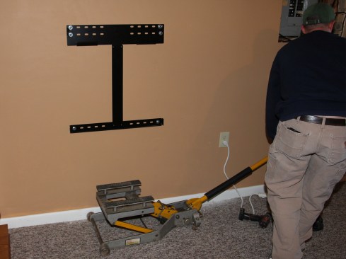
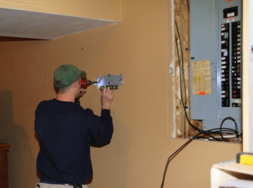
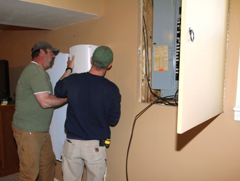
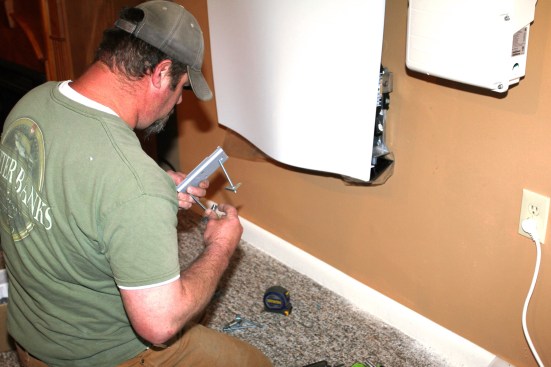
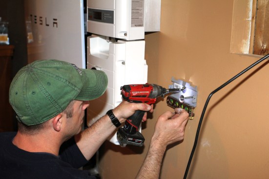
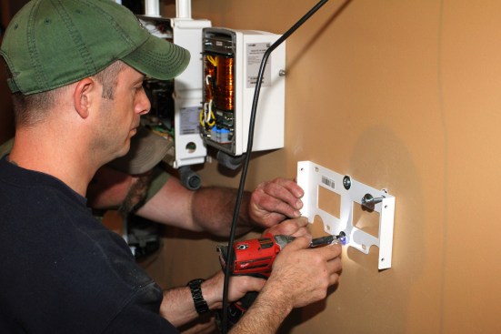
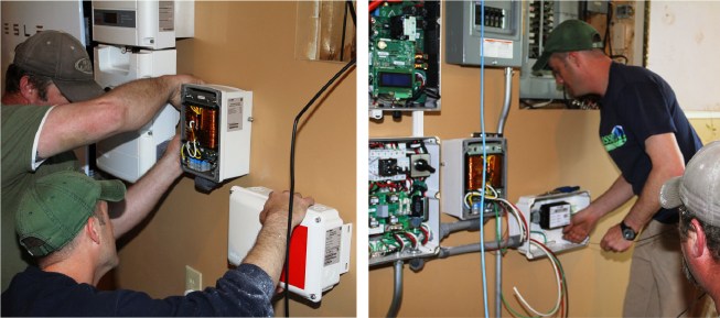
The Powerwall mounting bracket bolts to the wall studs.
And as JLC learned from GMP executive Josh Castonguay, the Powerwall isn’t just a cool accessory for homeowners with solar panels on their roofs. Whether it’s paired with a solar array or not, GMP sees the Powerwall as a practical way to protect rural homeowners against local power outages, and also as a way for the utility to match the variable loads in its service area to the variable solar and wind sources that now make up more than 15% of GMP’s generating capacity.
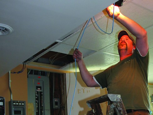
JLC recently went on site with electricians Scott Millette and Brian Ritz (Peck Electric, Burlington, Vt.), to see a Powerwall installed in a home. Millette has been installing and servicing electric-car recharging stations for GMP for several years. Putting in Powerwalls is a little different, he said, “but I have no trouble grasping it.”
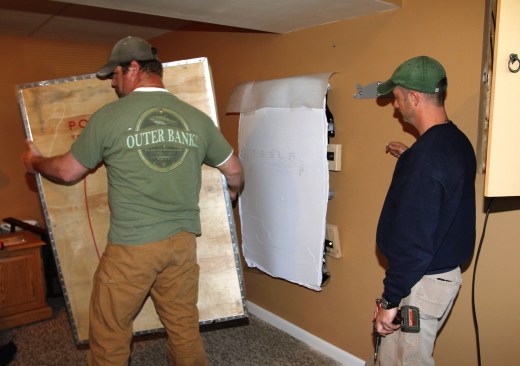
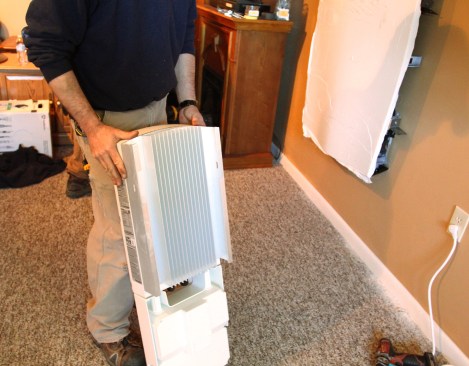
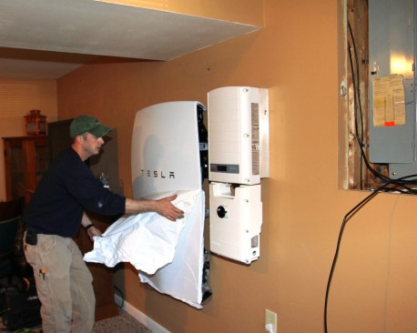
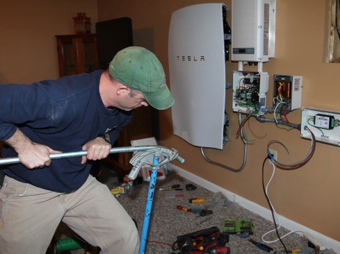
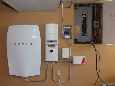
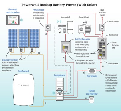
It’s not just the Powerwall. The Peck Electric crew needs to install a whole assortment of components to support the battery’s multiple functions (see illustration). The heart of the system, of course, is the battery itself—a 214-pound, 51.3-inch-by-34-inch-by-7.2-inch unit that arrives in its own plywood crate. The electricians bolt a steel mounting rack to the wall, jack the battery into place, attach it, then remove the crate and protective plastic wrap.
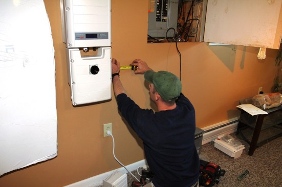
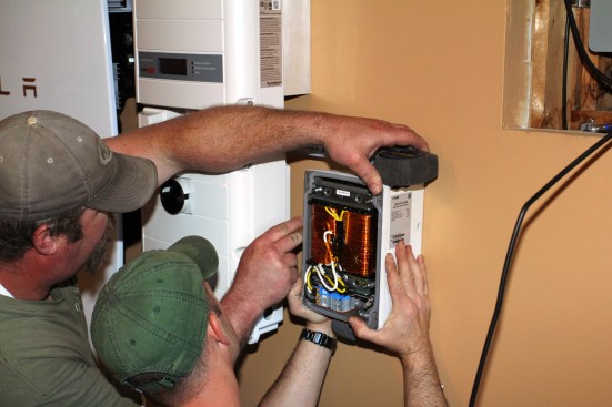
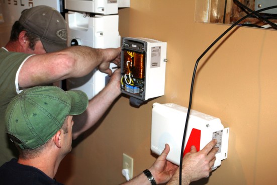
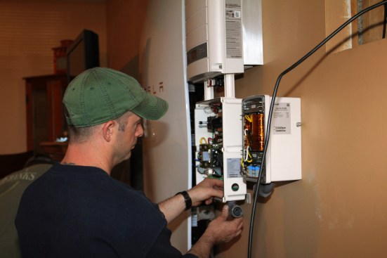
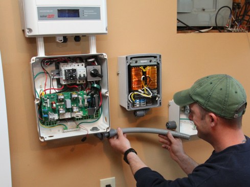
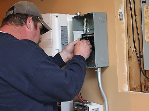
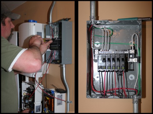
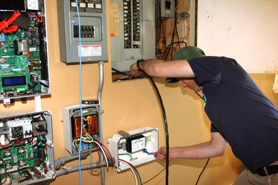
Next, the installers mount a “StorEdge” inverter supplied by SolarEdge, a major manufacturer of inverters for home solar systems. The inverter converts DC to AC power and vice versa, as needed to charge the battery or to draw power from it. The inverter has two modules: one that does the current conversion, and one that handles switching to feed power into the battery or draw power out of it, and to direct AC current to household backed-up loads, main loads, or into the grid. Wired to the inverter is a small transformer serving the backed-up circuits (this component is necessary to provide consistently regulated 120-volt current and grounding). In backup mode, the transformer feeds regulated power through the “load center”—a small breaker box similar to a subpanel, with circuit breakers for the individual backed-up circuits in the home.
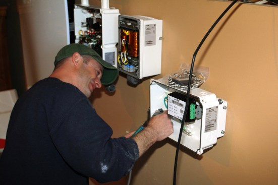
Helping to manage all these devices is a “smart meter,” which monitors and reports on current flows throughout the system, enables GMP technicians to communicate with and control the battery and the inverter, and alerts the power company to any malfunction.
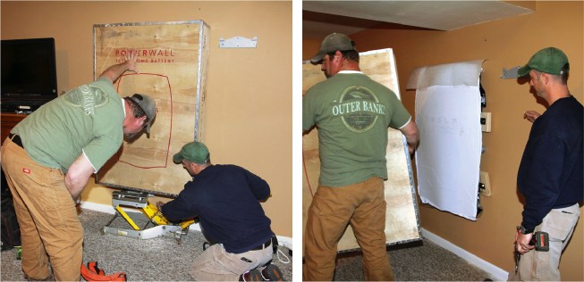
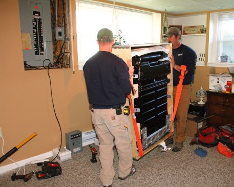
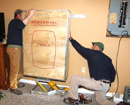
The Powerwall in its plywood shipping crate is jacked up and mounted, then unboxed.
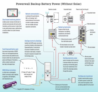
The example shown here is a simple backup power system for a house with no site-generated energy. If the house did have solar panels, they too would be wired into the inverter. In that case, the electricians would also equip each rooftop module with its own “power optimizer” designed to improve the efficiency of the inverter. The smart controls would allow the power company to direct solar-panel output as needed to household loads, into the battery for later use, or out to the street.
Click here for larger image
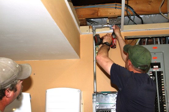
Grasping the ins and outs. By the middle of May, Scott Millette had installed seven Powerwalls—“probably more than anybody else in the country,” he told JLC. With a three-man crew, he said, the process takes about a day and a half. “It’s actually a very user-friendly install,” Millette said. “With every install, we learn new tricks, and the process becomes easier. But it’s not difficult.”
Non-electricians, however, may not find the Powerwall setup so easy to understand. In principle, a battery is simple: It’s a power storage device. You can charge it up, and you can run it down. But a house-mounted Powerwall is a little more complicated than that, because it’s capable of serving multiple functions—which is why it comes with an elaborate control system.
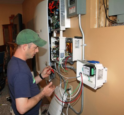
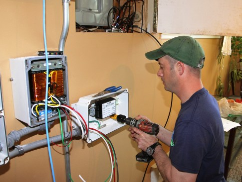
With the Powerwall battery and StorEdge inverter in place, the electricians add a transformer (which regulates voltage and improves efficiency and power quality) and a SolarEdge smart meter (which communicates between the equipment and the utility and homeowner).
For starters, if the electric company offers off-peak rates, the battery could store up power during off-peak periods and let the homeowner use that power during on-peak periods. Or, if the homeowner has solar panels, the battery can store up solar power during the day so the homeowner can use it at night, when there’s no sun. The battery can also provide limited backup power to a house in case of a “service interruption,” or power outage (the main selling point for most people).
That emergency backup function is nice—and it’s multiplied many times over for houses that do have solar panels. Homeowners are sometimes surprised to learn that “grid-tied” solar panels usually don’t serve as backup power during an outage. Typically, the panels are set up to cooperate with the grid—and when the grid goes down, the panels quit working too. But in a Powerwall-equipped house, the panels can stay engaged; the battery and its associated control systems serve to smooth out the peaks and valleys created by intermittent sunshine, and keep a steady supply on hand for the house. So if a weather event or some other mishap knocks out a home’s utility service, solar panels paired with the Powerwall could keep the home running indefinitely, at least on partial power.
The utility side. But all that is still only half the story. Battery storage also offers value to the power company—that is, if they can share the control of it. Even before Powerwall came along, Green Mountain Power was already investing in battery storage—not for one house at a time, but on a utility scale. The Stafford Hill Solar Farm, built on a landfill in Rutland, Vt., has 7,700 solar panels covering 15 acres of land. That’s 2 megawatts (MW) of power in full sun, and it’s coupled to 4 MW of battery storage in a local microgrid. The microgrid is connected to a Rutland high school, providing an emergency shelter in case of a disastrous power failure.
The U.S. Department of Energy put up seed money for the Stafford Hill project, but GMP invested the lion’s share of the project’s cost. Vermont regulators approved—because GMP persuaded the state that it will quickly earn its money back and reap savings for ratepayers. That’s because GMP gets charged an annual “capacity” fee by regional power-grid managers, based on the power Vermont pulls from outside providers during the region’s annual peak hour of use. The fee is Vermont’s share of the cost of keeping generating plants on standby so that peak loads won’t overwhelm the system. If the utility can supply its own standby capacity and call on its big battery bank to help out during that one peak hour of the year, it can avoid some of that penalty fee.
The utility can also reap value by purchasing power when it’s cheap, and storing it for use during high-cost periods (what’s called “arbitrage”). GMP generates a lot of its own power, but it also buys power from other suppliers on the regional grid. The prices for that purchased power can change by the hour, as demand fluctuates. In fact, late at night when demand drops off, some regional generating companies who operate plants that are hard to shut down are stuck with extra power that they have to get rid of, even if they have to give it away—or even pay someone to take it. So with its big battery bank at the ready, GMP can sometimes get paid money at 2 a.m. to store power that it can turn around and sell for full price at suppertime the next day.
Click here for larger image
Batteries are also an effective way to perform a function called “frequency regulation” on the power grid. Alternating current is supposed to be generated and transmitted in a nice, uniform wave-form at 60 Hz (60 Hertz, or 60 cycles per second). But a lot of factors can create interference and distortion on that smooth wave—noise that can impair the function of motors or electronic devices. Very well-controlled power generators, such as some gas-turbine power stations, can help “clean up” that “dirty” power on an entire network. But it turns out that batteries are the best frequency-regulating technology going. GMP could get paid by other utility providers to use its Stafford Hill facility to help clean up grid power—not a huge income stream, but something the power company is considering.
A distributed solution? All these functions, in theory, could also be performed by batteries like the Powerwall, scattered around in houses—as long as, that is, the batteries can be centrally controlled, or “dispatched,” by the power company. And that’s where Vermont’s “smart grid” comes in. GMP has already installed “smart meters” throughout its service area. Long run, the utility could use its web to manage thousands of scattered batteries and solar panels, as well as managing local loads—for instance, turning electric water heaters on and off as supply and demand on the grid fluctuate—to smooth out consumption and production curves, and potentially save money for everyone using the grid.
For now, GMP is focusing on the power backup and load-shaving potential of the Powerwall, and it’s proposing to share the cost with homeowners based on that split. The homeowner pays part of the cost of the battery and gets a few hours of backup for critical loads if the power goes out. The power company pays for another share of the cost (as well as financing the deal), and in return gets some ability to “dispatch” the battery for its own purposes: avoiding capacity charges for peak use, and buying and storing cheap power during off-peak hours. If consumers prefer, they can buy the battery outright and not share control with the utility; but GMP expects most people to opt for the sharing arrangement instead.


