by Gordon Tully
Houses built directly on the beach are subject to periodic damage from large storms. The most destructive element of a major tropical storm is the surge — the bowl of water that rises around the center of the storm. In fact, storm surge coming ashore as powerful waves were responsible for the worst damage in Hurricane Ivan in 2004, and this year the surge from Hurricane Katrina literally wiped out the Mississippi and Louisiana shorelines.
Under the National Flood Insurance Program, the feds long ago mandated special regulations for construction along the shore to prevent large flooding claims. If a home is entirely or partly within the wave “velocity zone” (V-zone), as shown on the Federal Insurance Rate Map, it must be built on sturdy piers so that the underside of the support structure is above the predicted surge level for the area. Everything built below this safety level must be either strong enough to resist the force of the waves or weak enough to safely “break away” and disintegrate under wave action. In order for a community to be eligible for federal flood insurance, its building code must incorporate these standards.
As it turns out, forensic analysis following the 2004 and 2005 hurricanes suggests that while some surge may simply be too great to build against, most homes built to federal standards did survive the surge.
Several years ago, I designed a home for a V-zone site. I want to pass on some observations concerning the special problems encountered with this type of construction.
CONCRETE PIERS PREFERRED
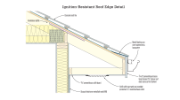
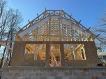
While it is possible to drive pilings to support the elevated structure, a poured-in-place concrete structure proves more effective for both aesthetics and security. My engineer employed a clever scheme using 16-inch-square concrete flue blocks as piers, filled with concrete and rebar, topped with a grid of concrete beams (Figure 1).
Figure 1. A grid of reinforced concrete beams creates a “table” to hold the wood frame structure (left). The concrete block walls underneath are designed to break away from the support columns if battered by storm surf (right).
Conceptually, the structure resembles a table. The pier “legs” are tied together with grade beams to avoid movement caused by the scouring action of the waves, a critical issue. You’ll need a good engineer to work out the reinforcement and forming for this type of structure. It is not particularly expensive if the engineer is familiar with the work.
Why not build such a table-like structure out of wood? Besides the issues of durability and resistance to the impact of floating debris, wood connections are the weak link. Wood joints designed to resist tensile and compressive forces tend to loosen up when left exposed to the weather, especially at the seashore. The wood can split, holes can enlarge, and water can get into bolt holes and soften the wood.
Atop the “table,” you can erect ordinary framing. But it is important to tie the structure down to the concrete support grid. My engineer used wood plates anchored into both the top and bottom of the concrete beam. The plywood wall sheathing then runs past the side of the beam and is nailed to both plates.
DESIGN SOLUTIONS
It would be simple to merely set an ordinary house on top of this raised concrete foundation. You can very easily cantilever the concrete beams out beyond the house to support a deck. Elegant, no?
Unfortunately for such simplicity, an ordinary house sitting on a bunch of stilts looks as uncomfortable as it sounds. Standard house designs are proportioned to look good on the ground, not a full story up in the air. A cantilevered porch adds visual insult to injury.
Historical precedent. Rather than try to invent the wheel, I looked to history to help us produce a satisfying building form while working around the engineering requirements. There are very few historic precedents for buildings on stilts and even fewer for those of a modest, residential scale.
Probably the most useful are certain French Colonial homes, which have large porches surrounding the living spaces, with sheltering hip roofs extending out to the edge of the porch, supported by a two-story arcade (Figure 2).
Figure 2. Fortier Design. The wide eaves carried down to the ceiling level make this French Colonial look well proportioned.
There are two important visual lessons to be learned from such houses:
Bring the eaves down to the ceiling level of the main (now second) floor, so the house will not look tall and uncomfortable.
Make the structure extend to the outermost part of the house — no cantilevered porches.
The French Colonial examples were not exact prototypes for my design. For instance, the lower floors were closed in and occupied in the Colonial example, whereas there can be no usable space on the lower floor of a house in the velocity zone. Also, the deeply shaded porches and recessed walls are a response to the hot, humid climate in the Colonial example. In my northern region, the need for winter sun and a wider deck cause the eaves to be set back from the edge of the porch on two sides in my design. Nevertheless, the overall visual effect of the southern prototype was an excellent guide.
Another more monumental approach is to create an arcaded base, as in the example shown, a wing of a Virginia mansion, known as Bremo (Figure 3). The key design guideline here is to cut the arcade out of the building facade, so that the main floor is set back from the support structure — no cantilevers. In my interpretation, I added gussets at the top of the porch posts to suggest an arched opening. Note that a full arch would effectively increase the area of the porch posts and increase the resistance to wave action.
Figure 3. Bremo Design. The arcaded base of the Bremo house suggested a treatment for the substructure.
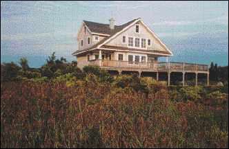
My interpretation. My design (Figure 4) extends a porch around two sides of the small house, with an arcade of wooden posts supporting the outer edge of the porch. The wide eaves of the gable roof come down as low as possible, imitating the horizontal lines of the porch. The effect is an extended base topped by a massive, floating roof. Thus, the height of the house, extending right up to the 35-foot height limit, is disguised: It looks like an ordinary two-story house sitting on the ground.
Figure 4. Tully Design. The low, wide eaves of the Tully design — reminiscent of the Fortier house — work with the extended porch to disguise the true height of the building.
BREAKAWAY WALLS
After considering various kinds of panels, I ended up with the enclosure recommended by FEMA (1986 edition) and embraced by my engineer: This consists of a wall of unreinforced (but mortared) concrete block masonry units (CMUs). To make the problems associated with breakaway construction clear, consider the following wall panel scenarios:
Suppose that the wall panels do not break away from the structure when hit by a wave. The pier suddenly “looks” to the wave as if it were a full bay wide, perhaps 12 feet, instead of its real width of 16 inches: It must resist eight times the load from wave action.
If, however, the wall breaks away at the usually required 20 psf, the column experiences only a little more than the design wind load before the panel falls away (20 psf corresponds approximately to a 75-mph wind).
To achieve this result, the wall panel must not catch itself on or jam itself within the structure. To this end, a 2-inch gap is necessary between the panel and the columns at each side. You can cover the gap, as long as the covering will let go and get out of the way (Plan View, Figure 1).
How can a panel be designed to break away at a particular loading? The method I devised was to stiffen the top edge of the panel and attach it to the structure by a few carefully designed 1/2-inch stainless-steel breakaway pins. The CMU wall is topped with a continuous bond beam in which are embedded two pins, one at either end (Beam Detail, Figure 1). The diameter of each necked-down section was calculated so that the ultimate strength at that diameter equaled half the load needed to topple the wall. Even if the pins are made with stainless steel, the owner should have them examined periodically for rust, and replaced if corroded.
Once a panel falls away, it should break up into small pieces. CMUs are ideal: They simply fall down and stay more or less put. Wood panels are much harder to design, as a typical stud wall with plywood skin will stay intact if waves break it away, and this floating raft will wreak havoc among the structural supports.
To improve the aesthetic appeal of the base of the house, I chose to disguise the block by attaching wood battens to the CMU wall at 8 inches on-center. These battens also close the gaps at the ends of the infill panels. The shadows from the raked horizontal block joints combine with the strong shadows of the battens to create a nice grid pattern.
DETAILS THAT MAKE IT WORK
In order to enter such a house, the breakaway concept has to be compromised by the introduction of a permanent stairway. In this case, I left the risers open, surrounded the stair with a breakaway wall that must fall outward (it luckily points away from the water), and put the front door at the top of the stairs. Some code officials might allow a permanent full enclosure for the stair, but it seems to me such a structure is asking to be battered to pieces in a severe storm. A second stair is off the deck, where it can be heaved up out of harm’s way like a gangplank whenever the house is not occupied (the stringers are spindled on a pipe at the top).
The client had a split reaction to the absence of a visible front door. It didn’t bother the husband, but it did bother the wife. At one point, they were thinking of extending the stair to include a ground-floor entry hall.
Insulation is a consideration, too. The underside of the main floor must be heavily insulated, like a roof, by upsizing the joists (2x10s or 2x12s). Keep any horizontal plumbing at the top of the insulation: It is probably okay in most cases to cut the tub drain into the top of the (oversized) joists, but check with the engineer.
I ran all the house ductwork in the ceiling of the main level to avoid heating ducts in the floor, knowing that no matter how hard you try, the ducts will not be properly protected if placed in the insulated floor. — Gordon Tully is an architect in Norwalk, Conn., and teaches a summer executive education course at the Harvard Graduate School of Design. Photos and illustrations by the author, except where noted.
Sources of Information For more examples of historic precedents, consult the indispensable A Field Guide to American Houses, by Virginia and Lee McAlester, published by Alfred A. Knopf and available in paperback for about $20. The bible on this subject is the Coastal Construction Manual published by the Federal Emergency Management Agency (FEMA), Document FEMA-55 (available by calling the FEMA Publication Distribution Facility at 800-480-2520). |