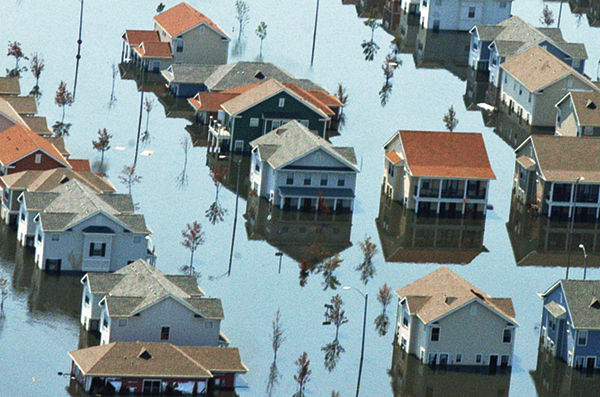
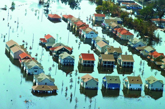
Photo: Liz Roll/FEMA
In This Series
Wildfire-Resilient Buildings
Flood-Resistant Buildings
Earthquake-Resilient Buildings
Wind-Resilient Buildings
Strategies for rendering homes resilient to floods vary by whether the site is subject to coastal wave action or (in the case of most inland flooding) at risk of immersion in still or slow-moving high water.
Coastal Conditions
Waves can exert enormous loads on buildings. While winds wield pressures in the tens of pounds per square foot, a 2- to 3-foot wave can exert pressures in the hundreds or even thousands of pounds per square foot. Waves that break at a structure create the most intense impacts; wave outflow and ocean currents running diagonally to the shoreline mean structures get hit from all sides. No ordinary wall can resist such a combination of forces. But despite the magnitude, protection proves relatively straightforward: elevating structures above the wave action and allowing the water to wash harmlessly under the building. In storm after storm, inspectors assessing damages report that homes elevated on pilings survive relatively unscathed compared with older homes supported by solid foundations.
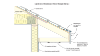
In V zones (“V” stands for “velocity wave action”—think oceanfront sites that can be overrun by waves 3 feet and higher) and Coastal-A zones (further back from the coastline but still subject to waves up to 3 feet high), the lowest portion of the first-floor framing must be elevated above the base flood elevation, or BFE. The height of the BFE is determined by a statistical analysis of the last 100 years of measured stillwater elevations and calculated heights for waves and wave runup (the rush of water up a slope or structure caused by breaking waves). In V and Coastal-A zones, no permanent enclosures are allowed below the first floor. Some community building codes may go beyond this by identifying a design flood elevation (DFE) above the BFE. The height exceeding the BFE is called a “freeboard” (see illustration, below).
![In V and Coastal-A zones, no permanent enclosures are allowed below the first floor. Some community building codes may go beyond this by identifying a design flood elevation (DFE) above the BFE. [Illustration adapted from FEMA P-499 (Dec. 2010): “Home Builder’s Guide to Coastal Construction”]](https://www.jlconline.com/wp-content/uploads/sites/4/2025/06/0422-jlc-flood-web-01.jpg?w=319)
Illustration adapted from FEMA P-499 (Dec. 2010): “Home Builder’s Guide to Coastal Construction”
In V and Coastal-A zones, no permanent enclosures are allowed below the first floor. Some community building codes may go beyond this by identifying a design flood elevation (DFE) above the BFE.
The height of the foundation is only one factor in coastal-storm resilience. A building’s structural integrity also depends on the depth of piling embedment and the quality of connections between the piling and the framing.
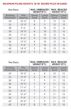
Example piling heights based on Texas Dept. of Insurance Building Code for Windstorm Resistant Construction.
Embedment. Unlike a foundation that rests on a footing, most driven piles support loads by friction along the length of their sides. The embedment depth depends on the soil characteristics, and most jurisdictions require an engineer’s soil analysis. A typical pile length for residential homes is between 20 and 60 feet.
The piling embedment specified by the engineer must account for predicted scour, the erosion around a fixed object. If the soil erodes around piles in a storm, the remaining embedment must be sufficient to resist uplift and provide lateral support.
Girders and joists. Ultimately, all loads must resolve to the pilings by way of girders, blocking, and often cross-bracing. Because of the complex load paths involved and the likelihood that the home will be tested by high winds, water, and impact from waterborne debris, most jurisdictions require that the entire structure be engineered.
Because of the difficulty of driving pilings perfectly plumb, the outer pilings of a foundation array are usually placed 6 to 10 inches in from the building line. This means the joists will cantilever a short distance beyond the girders. As a rule of thumb, the cantilever distance should never exceed the girder or joist depth.
Girder connections. When a piling foundation fails in a storm, it’s usually because the connection at the top of the piling fails, which causes the house to wash off the foundation. A strong connection between piling and girder requires a notch in the piling and several galvanized 3/4- or 7/8-inch-diameter steel bolts. Although it might seem easier to simply cut the tops of the pilings flat and use metal straps to secure the girders, that is more complicated to do well and ultimately takes more time.
The notch for a piling-to-girder connection should not be deeper than half the cross section of the pile. As with the overall structural design, the connections must be specified by an engineer for V-zone foundations.
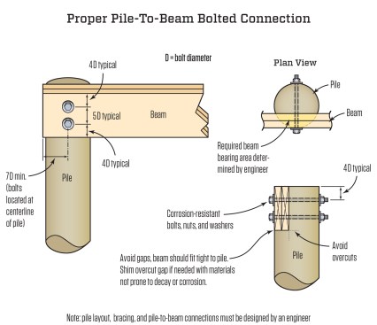
Piling connection details adapted from FEMA P-499 (Dec. 2010): “Home Builder’s Guide to Coastal Construction”
Bracing. Cross-bracing at the pilings may be necessary to resist lateral loads from wind or water. However, the cross-bracing may also catch debris and impede the flow of water, increasing the load on the foundation. As an alternative to an extensive amount of cross-bracing, a larger pile and closer spacing will allow for an increase in unbraced piling height. If cross-bracing is used, it’s best to install it perpendicular to the shoreline, so the bracing does not become a barrier to incoming waves.
Building Resources:
Coastal Construction Manual: (PDF): FEMA P-55 (2011)
“Home Builder’s Guide to Coastal Construction” (PDF): FEMA P-499 (2010)
Building Science Corp. "Designing for Floods": BSI-128
Raised Wood Floor Foundations Design & Construction Guide (PDF): SFPA 411 (2017)
Inland Flood Resilience
Riverine flood areas are defined by the National Flood Insurance Program (NFIP) by a range of zones on flood maps, and terms have changed. BFE is defined locally by likely flood elevations without wave crests or runup. Zone A is the designated area for a 100-year flood (a 1% chance of such a flood each year); it is the only inland zone with a defined BFE. Zones B and X are shaded areas on a flood map at moderate risk of flooding. Zone X can also be unshaded; along with zone C, this area is at low risk.
Solid foundations are the norm in most inland flood areas, and while they may not see the intense force of waves, they can see lateral hydrostatic loads from standing or slowly moving floodwaters. If the water level on one side of a foundation wall is much higher than on the other, the wall must resist an immense load. The answer for many crawlspace walls in flood-prone areas is to install flood vents, which are designed to open under hydrostatic pressure. The flow of water inside equalizes the pressure on each side of the wall, providing relief.
![If the water level on one side of a foundation wall is much higher than on the other, the wall must resist an immense load. The answer for many crawlspace walls in flood-prone areas is to install flood vents, which are designed to open under hydrostatic pressure. [Illustration adapted from Building Science Corp. BSI-128]](https://www.jlconline.com/wp-content/uploads/sites/4/2025/06/0422-jlc-flood-web-05-rev.jpg?w=653)
Illustration adapted from Building Science Corp. BSI-128
If the water level on one side of a foundation wall is much higher than on the other, the wall must resist an immense load. The answer for many crawlspace walls in flood-prone areas is to install flood vents, which are designed to open under hydrostatic pressure.
For vented crawlspaces, most building codes require air vents sized at least 1 square foot of net free area for each 150 square feet of crawlspace area. NFIP prescriptive requirements for flood vents call for at least 1 square inch of net free area for every square foot of crawlspace area, with two vents per enclosed area on different exterior walls. The required flood vent sizing is slightly more than the air-ventilation requirement—a detail to note when non-engineered flood vents double as air vents in a short crawlspace.
![The wall in the upper portion of the wall is for ventilation air, as required by code. The vent lower on the wall- (preferably at grade) is designed to open under hydrostatic pressure to prevent the wall from toppling. [Illustration adapted from Building Science Corp. BSI-128]](https://www.jlconline.com/wp-content/uploads/sites/4/2025/06/0422-jlc-flood-web-06.jpg?w=214)
Illustration adapted from Building Science Corp. BSI-128
The wall in the upper portion of the wall is for ventilation air, as required by code. The vent lower on the wall- (preferably at grade) is designed to open under hydrostatic pressure to prevent the wall from toppling.
For tall crawlspaces in areas with a high BFE, the best solution we have seen is to provide flood vents lower down (codes specify placing all flood vents not more than 1 foot above grade) and position required air vents high on the wall for increased circulation. (For more on building a tall crawlspace, see “Rebuilding a Flooded House” by Dave Yelovich, Nov/18.)
Sealed crawlspaces are generally seen as ineffective in flood-prone areas, and most building scientists recommend you focus efforts on air-sealing and insulating the first floor. However, two companies—Smart Vent and Flood Flaps—make engineered flood vents for use in sealed crawlspaces and conditioned enclosures on slabs.
Utilities, including heating and cooling equipment, water heaters, fuel tanks, electrical panels and well heads, are all at risk of damage from floods, and the primary approach to protecting them is elevating them to the “flood protection elevation,” or FPE, with a freeboard typically defined by local jurisdictions. With HVAC, it’s not only the equipment but also combustion air, fresh air intakes, and ductwork that must be placed above the FPE. This holds true for all vents, including those on fuel tanks.
Wells can be drilled in flood-prone areas, but building codes usually require a watertight sanitary well seal and a steel sleeve extending above the flood protection height and at least 24 inches below grade.
![In A-zone flood regions, heating and cooling equipment, water heaters, fuel tanks, electrical panels and well head should all be positioned the flood protection elevation (FPE) specified by local code jurisdictions. [Illustration adapted from Accomack County (Virginia) Flood Program]](https://www.jlconline.com/wp-content/uploads/sites/4/2025/06/0422-jlc-flood-web-04.jpg?w=587)
Illustration adapted from Accomack County (Virginia) Flood Program
In A-zone flood regions, heating and cooling equipment, water heaters, fuel tanks, electrical panels and well head should all be positioned the flood protection elevation (FPE) specified by local code jurisdictions.
Flood-Hardy Construction
Ideally, all homes in flood plains should be built above the anticipated flood level. But even for new construction, that’s an expensive proposition. And the cost of raising existing homes above the flood line is usually prohibitive, especially if the house is built on a slab foundation. The alternative is what FEMA calls “wet floodproofing” (commonly dubbed “flood hardy” or “wash and wear” construction). Many of these strategies were pioneered by Joe Lstiburek of Building Science Corp. and championed by Claudette Reichel at the LaHouse demonstration home built by the LSU AgCenter. The initial design (see illustration, below left) was developed for rebuilding flood-damaged homes to make cleanup from future flooding events easier. The strategy was further developed by Lstiburek for new construction (below right).
![When it is impractical to elevate buildings, the lower, flood-prone areas of the building can be built or retrofit with materials that will withstand getting soaked once they dry out. [Illustration adapted from LSU AgCenter (left) and Building Science Corp (right)]](https://www.jlconline.com/wp-content/uploads/sites/4/2025/06/0422-jlc-flood-web-07.jpg?w=514)
Illustration adapted from LSU AgCenter (left) and Building Science Corp (right).
When it is impractical to elevate buildings, the lower, flood-prone areas of the building can be built or retrofit with materials that will withstand getting soaked once they dry out.
The goal in both cases is drainable and dryable building assemblies, using building materials that don’t fall apart when they get soaked and that can be easily cleaned and dried after a flood. For example, ordinary drywall is replaced with painted wood or cementitious panels, and fiberglass batts or cellulose cavity insulation is replaced with closed-cell spray foam and rigid insulation boards. Electrical fixtures and wiring also get destroyed when immersed in water, and the paper insulation in Romex wicks water far up the lines. To reduce the chances of this happening in a flood, outlets need to be placed higher on the wall.
Floodwaters tend to be filthy, so the interior side of the wall should be designed to be opened up, scrubbed, rinsed, and disinfected. In any flood, the extent of the damage and the demolition required will vary depending on how deep the floodwater is, how dirty it is, and how long this water sits in the house. In some cases, the interior wallboard may have to be completely stripped out. In others, only the lower wall may need gutting. In a best-case scenario, homeowners might be able to just remove strips of material and flush out and dry the walls.
Reconstruction after a flood will vary depending on the type of construction. For example, the solution shown below left was developed by Lstiburek to help rebuilding efforts following Hurricane Harvey in Houston, where brick veneer exteriors and slab foundations are common. This assembly creates a drainage and drying gap behind the brick, outboard of the insulated wall, using an open-weave or dimpled drainage mat against the brick. The base of the wall is coated with fluid-applied flashing to create a drain pan at the bottom of the wall. Weep holes in the bottom course of brick allow water to exit the cavity.
Paul LaGrange, a Louisiana-based building-science consultant, and JLC contributor Bill Robinson adapted the Lstiburek techniques to retrofit homes flooded during Hurricane Katrina in 2005, and in the Baton Rouge floods in 2016, where rebuilding efforts are still taking place. Some of the New Orleans homes were listed as historic properties, and on these balloon-framed homes, it often wasn’t feasible for crews to remove the existing “weatherboard” siding, so, as with the brick-clad Houston homes, crews worked from the inside to create robust air and thermal barriers and a drainage plane.
As shown below right, LaGrange took a cue from Lstiburek’s Houston design: He placed a drainage mat against the board siding, cut and fit sheets of XPS foam board, then applied closed-cell spray foam to air-seal the wall and lock the components together.
In both the Houston and Louisiana designs, the approach is the same: Building details employ materials that are not sensitive to water to reduce damage and make cleanup and repair easier the next time the building is hit by a flood. The centermost insulation layer is watertight and impermeable, while materials toward the inside and outside faces of the wall allow for drying.
![Two methods for retrofitting spray-foam insulation, which can withstand wetting, in the first-floor walls of older, existing buildings. [Left-hand design based on information from Joe Lstiburek, Building Science Corp., right-hand retrofit based on information from Paul LaGrange.]](https://www.jlconline.com/wp-content/uploads/sites/4/2025/06/0422-jlc-flood-web-08.jpg?w=535)
Two methods for retrofitting spray-foam insulation, which can withstand wetting, in the first-floor walls of older, existing buildings. [Left-hand design based on information from Joe Lstiburek, Building Science Corp., right-hand retrofit based on information from Paul LaGrange.]
All illustrations in this article by Tim Healey.