Figure 1. Approximately two years ago, my wife and I broke ground on a super-insulated home based on Passive House design, in Morrisville, Vt. We built the 1,000-square-foot home on property we owned with the notion of moving into it when we downsize our lives in the future (in the near term we plan to rent it out). And although we built it to meet PHIUS Passive House certification—adding saleable value—we’re not pursuing official PHIUS certification. Our goal was to build an attractive home that needs very little energy to heat in the winter and cool in the summer. With the help of Passive House consultant, Chris West of Eco Houses of Vermont, we built a cozy, aesthetically-pleasing home with the lowest heating bills modern building science can provide. The whole house has a heating load of approximately 3,200 Btu/hour at -2°F. The typical code-built house of this size has a heating load in the 50,000 Btu/hour range. For information about the detailing of home’s stone and cedar shingle cladding, see Backfill (Jun/16).
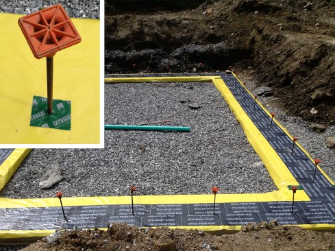
Figure 2. Strips of 10-mil Stego Wrap vapor barrier (yellow) were placed over the 40-inch-wide by 12-inch-deep footings. The strips were later used to join the Stego under-slab and foundation-wall membranes together. At rebar tie-in locations, the vapor barrier was air-sealed with Extoseal Finoc watertight barrier tape (see inset). A strip of Grace Vycor Plus was installed to protect the Stego Wrap where the foundation wall and interior, rigid EPS insulation met the footing.
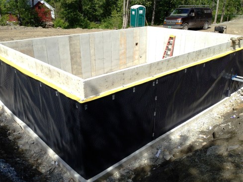
Figure 3. The 12-inch-thick foundation wall was poured with an 8-inch-wide shelf to support the stone veneer. Stego Wrap was run up the foundation’s exterior face and then folded onto the stone shelf. To protect the Stego from puncturing during backfilling, a dimpled drainage mat was installed against the wall. Later, 12-inch-thick EPS foam would be installed on the foundation’s interior, which would create a continuous insulation plane from the foundation up to the framed wall.
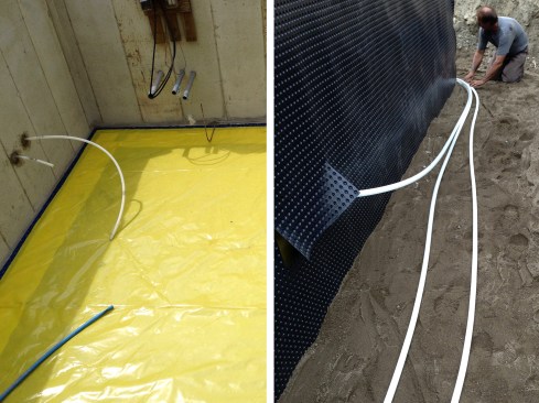
Figure 4. The Stego Wrap sub-slab membrane was taped around the perimeter to the strip run under the foundation wall (above left). All piping/conduit penetrations were sealed with hydraulic cement, then gasketed with Tescon Vana tape on both sides of the foundation. A 300-foot-long geothermal loop was installed around the perimeter of the house (above right). This loop will later be attached to a Zehnder ComfoFond geothermal heat exchanger, which will heat, cool, and maintain indoor-air quality and moisture control (a critical component to this air-tight home)
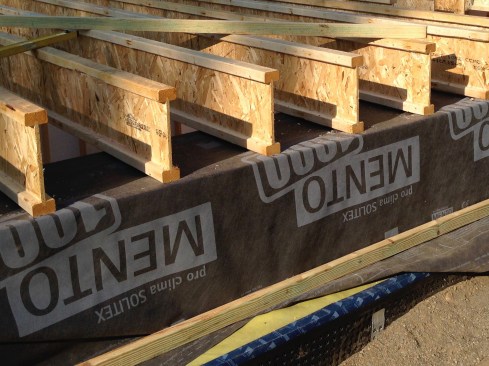
Figure 5. Prior to layout of the first-floor framing, a strip of Mento 1000 membrane was loose-laid over the basement’s EPS wall insulation and sill plates. The Mento was used to join the basement and first-floor Intello Plus air barriers together; the Intello smart membrane doesn’t function well when it’s cold, so the Mento is needed to make this critical connection (see illustration, below). To stop debris entering during backfilling, the top of the drainage mat was sealed to the Stego Wrap with Tescon Vana tape.

Click here for larger image.
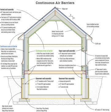
Figure 6. The house was designed with the Intello Plus intelligent vapor retarder—which has a perm rating range from 0.17 (closed state) to 13.7 (open state)—as the inner air barrier. For the outer air barrier, Solitex Fronta Humida WRB was chosen because of the stone veneer. The Humida membrane has a perm rating of around 8.0, which is sufficiently open for drying to the exterior while closed enough to stop solar-driven and inward diffusion. The rule of thumb in Vermont is that the exterior moisture barrier should be five times (5x) more vapor-open than the interior moisture barrier. This means that in the winter, when the vapor drive is from the inside of the house to the outside and the Intello’s perm rating is 0.17 (it’s in a closed state), the inner air barrier is forty-seven times (47x) more vapor-closed than the outer, Humida air barrier.
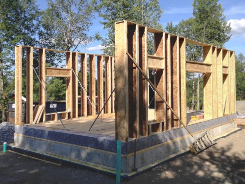
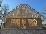
Figure 7. Passive House design often pairs 2x4 structural bearing walls with vertically applied wood I-joists for maximum cavity insulation. For this project, we wanted the wood I-joists to serve both our structural and insulation needs. And so, with our structural engineer’s blessing, we framed our high-performance “bearing” walls with 16-inch-deep wood I-joists—to our knowledge, this is the second home in the U.S. to so. Prior tilting up the walls, we folded the Mento membrane into place.
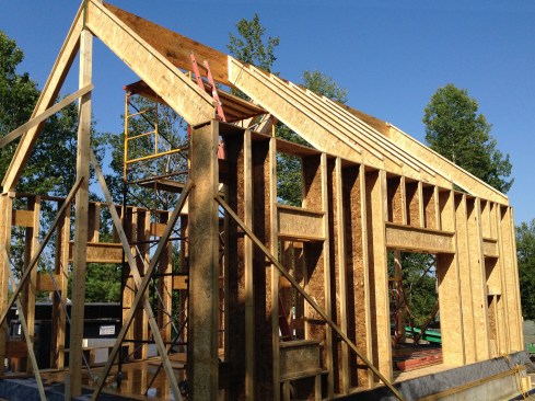
Figure 8. We framed the 10:12-pitched roof with 16-inch-deep wood I-joists, placing them in line with the wall framing. The resulting cathedral ceiling was later filled with dense-pack cellulose. For shear, we installed OSB gussets on the inside flanges of the I-joists (the exterior was sheathed with exterior gypsum board to help prevent racking). I-joists were installed above window and door openings to create open headers, which were easily dense-packed with cellulose.
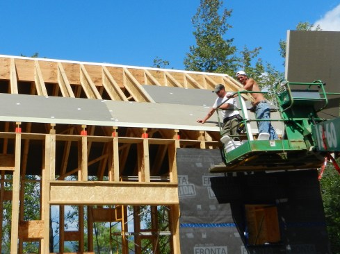
Figure 9. A double layer of 3-inch rigid polyisocyanurate insulation (with offsetting seams) was installed over the roof framing.
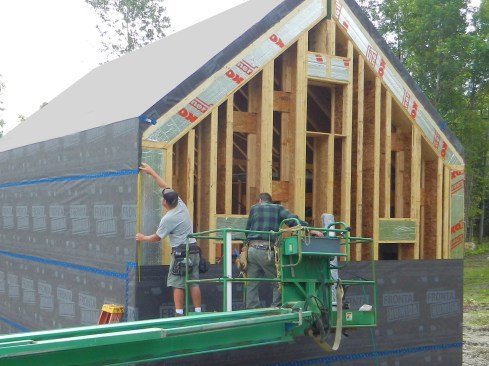
Figure 10. The Humida WRB was run up walls and over the roof plane. Rigid polyiso was fit into the I-joist flanges for a little more insulation.
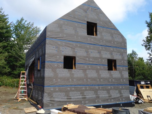
Figure 11. We lapped the Humida WRB down over the first-floor framing and foundation, down to the stone shelf, sealing all seams and fastener locations with Tescon Vana tape.
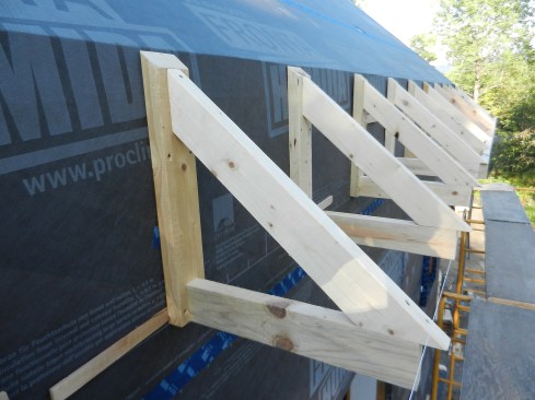
Figure 12. We built eaves brackets from 2-by stock on the ground and installed them outside of the building envelope.
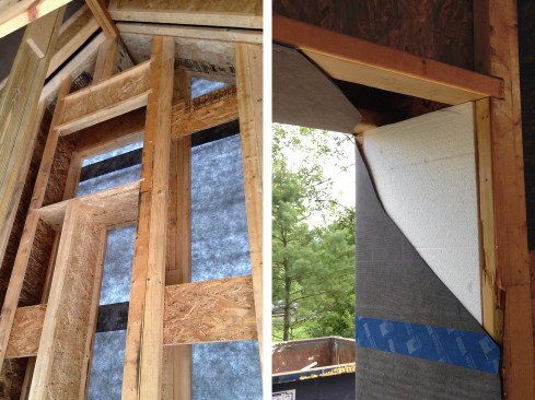
Figure 13. For shear resistance, we installed ¾-inch OSB gussets on the inside flange of the wood I-joists (above left). We offset their spacing, placing them at the same height in alternating stud bays. At window and door openings, we packed out the web of the I-joist with rigid polyiso and turned Humida WRB turned into the rough opening (above right).
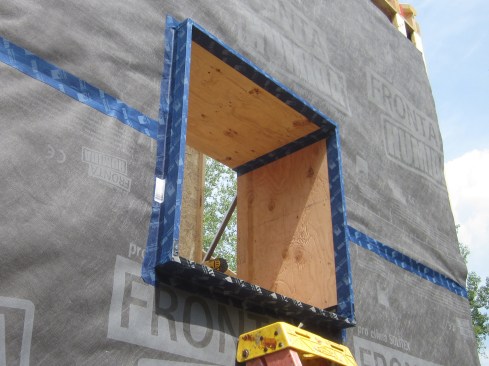
Figure 14. We used 3/4" CDX for the window bucks rather than OSB. I believe plywood is more resilient against water damage and slightly more vapor open than OSB. The bucks are sealed to the WRB with the Tescon Vana tape. We also tape the inside corners of the buck (for more info on buck installation and air-sealing, see Chris West’s blog on window detailing).
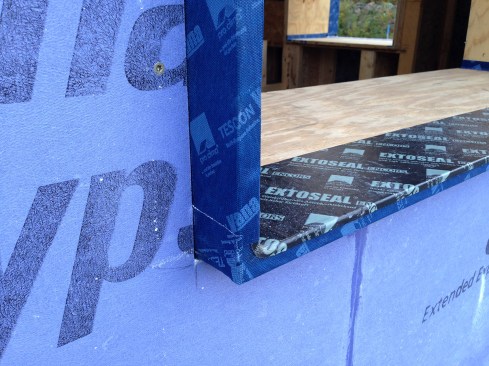
Figure 15. We used Extoseal Encors waterproofing tape to create sill pans for the window. Here, 5/8-inch-thick Gold Bond EXP sheathing by National Gypsum was fit around the window buck. Later, high-performance R-7 windows from PVC Industries were installed toward the outside edge of the window bucks, attached with metal mounting clips.
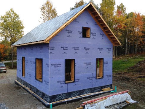
Figure 16. The Gold Bond sheathing is moisture and mold resistant and is vapor-open. It helps resist racking and it protected the Humida WRB against UV and the elements while the fieldstone veneer was slowly pieced together. Grace Ice and Water Shield covered the stone shelf, joining the WRB and drainage mat together. The finish roofing was installed (see illustration, above).
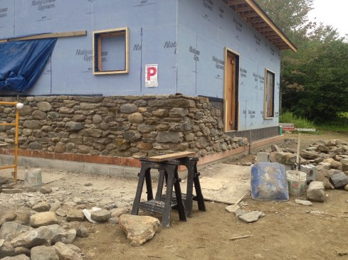
Figure 17. Two block courses brought the wall up to finish grade. Copper perimeter flashing was placed on top of the block with Cedar-Breather lapping its vertical leg. The fieldstone veneer was laid up with a roughly 2-inch air space between it and the Cedar-Breather and was tied back to the wall with masonry anchors fastened to the wood I-joists.
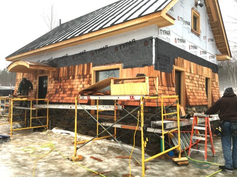
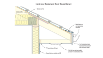
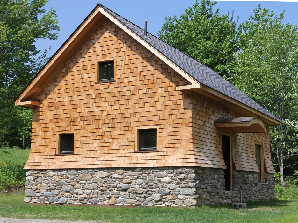
Figure 18. Originally, the home was to be clad entirely with fieldstone, but the stone proved difficult to work with and was taking too long to put up. We ended up shingling the upper portion of the wall, which in the long run, I believe, made for a better-looking home. We created a flared shingle detail, which made a nice, durable transition between the stone and shingles (see shingle flare detail).
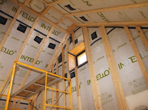
Figure 19. On the interior, Intello Plus was installed over the wood I-joists, and then the walls were furred out with 2-by strapping. Dense-pack cellulose was blown in from the inside. The electrical was run in the 1 1/2-inch furred-out space, and shallow electrical boxes were used to house the switches and receptacles.
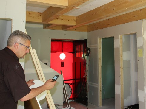
Figure 20. With the drywall installed, Jim Bradley, of Caleb Contracting, in Cambridge, Vt., performed the blower-door test in early June 2016 (Jim has to break out the blower door’s“D” ring—see video). The home averaged 76 cfm (65 cfm for depressurization and 87 cfm for depressurization), which translated to 0.45 air changes per hour at 50 Pascals—this is one really tight, high-performance country cottage.

Photos 2, 3, 4, 5, 7, 8, 11, 15, 16, 17, and 18 by Sean Gyllenborg
Photos 9, 10, 12, and 14 by Chris West
Photos 1, 19, 20, and illustration by Tim Healey