Math is fundamental to building. And while there is no escaping the need to be proficient with numbers and algebra, learning some geometry can go a long way in helping carpenters be more efficient. In this article, we’ll introduce a few methods for dividing, measuring, and laying out shapes that can save time and take some of the head scratching out of many layout jobs.
Scale. The first principle we’ll address is the idea of using a scale of known increments (such as a tape measure) to divide a line or area. In the first two examples below, we don’t need to know the width of the board we want to divide, or make any calculations. We simply hold the end of tape along one edge and run it out to the opposite edge. The distance and angle of the tape don’t matter, as long as we align the opposite edge with a number on the tape that we can easily divide by 2 or 3 (or any divisor we want). This same concept can be used to divide an uneven distance into a number of equal segments without having to pull out a calculator.
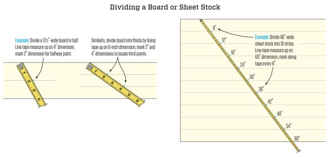
A tape measure provides a scale of even increments that can be used to divide any area (a board or piece of sheet stock, for example) into even distances. In the examples shown here, we are simply marking off evenly spaced tick marks, but you can measure square to the edge of the board to get the distance to set a rip fence, or to lay out a series of holes (or balusters or fence posts or pickets, and so forth) in a straight line.
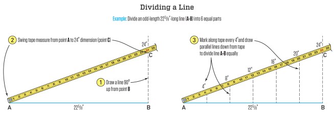
Similar to the method shown above, you can divide a straight line into even increments. In the example shown, the dotted lines extending from the even 4-inch increments are defined by using a square along the line AB.
Using a scale to mark off even segments can also be employed to laying out various curves, as illustrated in the examples below:
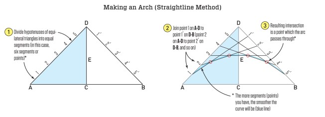
We can build on the use of a scale to divide the baselines (AD and DB) of two equilateral triangles (ADC and DCB). By snapping chalk lines between 1 and 1', 2 and 2', 3 and 3', etc., we can define the arc of a circle for a regular arch. As indicated, the more segments you define, the smoother the curve will be.
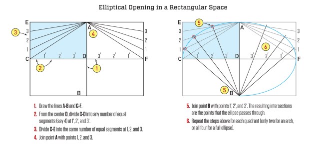
The easiest way to draw an ellipse is with the "pins and string" method (https://mathopenref.com/constellipse1.html). But this method can get unwieldy for large areas, on a vertical wall, or with masonry units. The method shown here, which relies on dividing lines on a rectangular area, might serve as an alternative layout method.
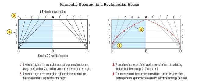
True gothic arches can get pretty complex, but a decent representation can be defined in a rectangular area, where CD defines the arch span and AB defines the arch height. By dividing the sides of the rectangle in even increments (as always, the more increments, the smoother the curve), two intersecting parabolic curves can be defined to form the archway. (Please note: This arch differs from a single parabolic curve, such as the Gateway Arch in St. Louis. That sort of arch can be drawn using a similar method that relies on divisions of the sides of a triangle, as demonstrated here.)
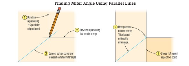
Angles are fundamental to joinery. Most of the time, we are dealing with right angles (90 degrees) and regular miters (45 degrees). What happens when we encounter other angles? Our inclination is to measure that angle in degrees somehow (with an electronic angle finder or a protractor, for example) because the table on a miter saw is set up with degree adjustments. However, a lot of times we don’t need to know the numbers. The miter for joining boards of unequal width, for example, is an acute angle less than 45 degrees, which we can lay out using parallel lines, as shown below. Once we understand this idea, we can just measure the width of one meeting board off the end of the other and join the diagonal.
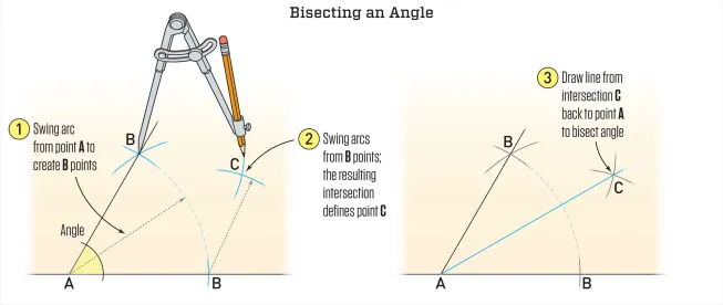
Or we can lay out any angle using a compass and a straightedge to bisect the angle as shown below.
If we do this on a scrap piece of wood, we can cut the angle we’ve drawn by aligning it with the blade on our miter saw—no numbers needed.
The same concept of swinging an arc (either with a compass or with a tape measure) can also be used to lay out different shapes, such as a square, a hexagon, or an octagon, as shown in the illustrations below.
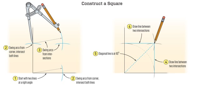
The illustration shows the construction of a small square using a compass. The same method can be scaled to a larger square using a string line and pencil. It's even faster to swing a tape measure, holding a pencil at the appropriate distance. Drive a screw at the zero distance mark, leaving it about 1/4 inch proud of the surface and let the slot in the hook of the tape measure ride on the screw head. This method is easier with a helper at one end of the tape measure.
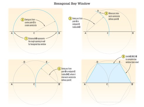
To lay out a hexagonal bay, start with the base of the hexagon AB. Bisect this line (or divide the distance in two and measure from one end) to define the center point C. This can be done on a sheet of plywood (if the baseline of the hexagon is less than 8 feet) or on a shop floor (to make a template for a larger bay) or on smoothly graded ground (if laying out a stem-wall foundation for a bay). To swing the arcs, use a tape measure or string line and a pencil.
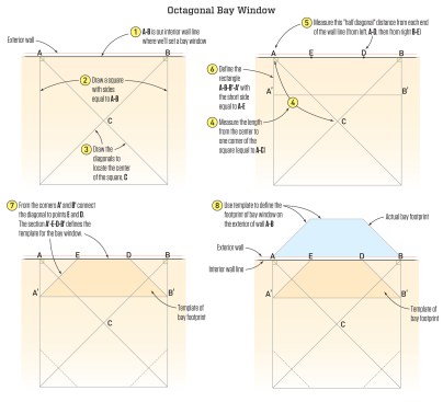
To lay out an octagonal bay window, you can work from inside the house or outside. In this set of illustrations, we are laying out a template on the interior. We start with what we know: the base of the octagonal section on the exterior wall, line AB. Inside the room, define a square with sides equal to AB, and define the diagonals to identify the center point C. Using the length of AC, measure from point A to define point D, and measure from B to define the point E. We can then measure AE, to define the distance AA' – the distance that the bay will project from the exterior wall. The measurements can be used to create a template of the bay window's footprint, or you can use a square and chalk lines to transfer the measurements to the exterior.
Leveraging the Pythagorean theorem. When we frame roofs or square large areas like a floor frame or lay out plates in preparation to stand walls, we can’t avoid the Pythagorean theorem: a2 + b2 = c2. If the abstract nature of this formula makes you nervous, it may be helpful to see the equation spelled out in geometric form, as shown below. (This visual explanation also gives us a construction of the square root function that maps the area of a square to its side length.)
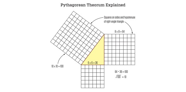
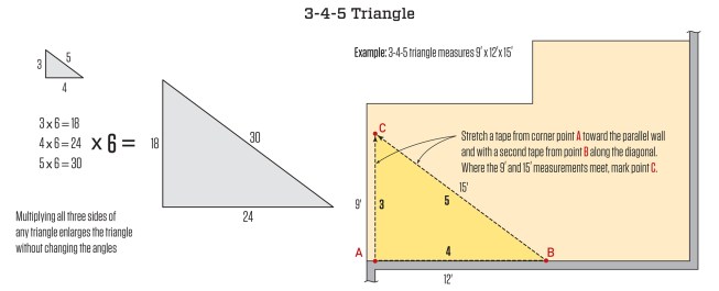
The example shown above is a 6-8-10 right triangle—a larger form of the all-powerful 3-4-5 right triangle; if one leg of a triangle measures 3 and the other 4, we know by the Pythagorean theorem, c = √ (a2 + b2), that the diagonal measurement, c, will be 5. But we don’t have to calculate this. Rather, we can use these dimensions as a check for square for any right angle: By measuring out one side equal to 3 units (inches, feet, anything) and the other side equal to 4 units, we know the hypotenuse connecting these sides will equal 5 units—or any multiple of 3-4-5: 6-8-10, 9-12-15, 12-16-20, and so on. When you’re squaring a floor or a foundation (see example, below), it’s always most accurate to use the largest multiple for the walls that you are laying out. For a more detailed explanation of this layout procedure, see “Framing Square Basics: Foundation Layout” by John Carroll.
The Pythagorean theorem relates to more than roof framing and right-angle layout; it can also be used to define the ellipse created where a vent pipe passes through a sloped roof. When the roof deck is part of the air barrier, we want to create a hole for the vent that can be tightly sealed.
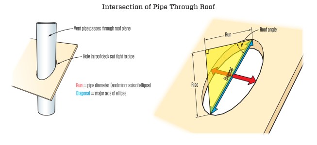
The width of the hole (defined by the thick red arrow) for a vent pipe through a sloped roof is the minor axis of an ellipse. It's the diameter of the vent pipe and it doesn't change; only the major axis (blue arrow) changes with the roof slope. The length of this diagonal can be solved using the Pythagorean theorem. So, for example, on a roof with a slope of 8/12, we could solve this using the unit run and unit rise: 82 + 122 = 208. The square root of 208 = 14.42, or 14 7/16. However, a vent pipe is unlikely to be a full 12 inches, so we need to reduce the numbers proportionally. For example, with a 3-inch-diameter pipe: 8/12 = x/3, where x = 2. Then solve for the diagonal: 22 + 32 = 13. The square root of 13 = 3.6, or 3 5/8.