In This Series
Framing Square Basics: Foundation Layout
Framing Square Basics: Rafter Layout
Framing Square Basics: Octagon Layout
When I first started doing carpentry in the mid-1970s, I had never seen a hand-held calculator. Like a lot of carpenters, I learned to do some layouts without using math. To do others, I figured out how to use the geometry stored on my framing square. Using the tables on the square often required multiplication and division, which I did with a pencil and paper. Using this method, I was able to lay out things like foundations and roof frames precisely, and I was usually able to do the necessary math in a few minutes because it was fairly simple.
I used geometry, to be sure, but I didn’t actually do geometry. The geometric proportions were etched on the framing square, and all I had to do was expand them using the multiplication I had mastered in grammar school. To do this, of course, I had to convert from fractions to decimals. Doing this, again, required grammar-school math, and after doing it for a while, I found it as easy and natural as driving a truck with a manual transmission.
More importantly, I learned how to visualize how the geometry stored on my framing square fit the structure I was laying out. For as long as I can remember, people have overstated the difficulty of the underlying math (especially of roof framing) and assumed that, once they overcame that obstacle, they’d be able to lay out foundations and roof frames. But the math is not the main obstacle. Almost everyone I know, whether they work in the trades or not, can do the math required for these tasks. What they struggle with is visualizing how that math can be applied to the layout.
In this article—the first of a two-part series—I’ll walk down memory lane in part simply to show how things were done before we had calculators and also to explain the meaning of the mysterious tables on framing squares. The main thing I want to show, however, is how geometry—whether it’s compiled in manuals such as Riechers’ Full Length Roof Framer, etched in the tables on a framing square, or stored in the electronic memory of a calculator—can be applied to a foundation; in Part 2, I’ll show how a framing square applies to the roof framing process. In my own career, making that connection was key to my development as a builder.
Understanding the Brace Table
A traditional framing square includes a number of cryptic-looking tables on both the blade (the longer, 2-inch-wide portion of the square) and the tongue (the shorter, 1 1/2-inch-wide portion). The rafter table on the front of the square is easy enough to identify (if not to interpret), while the brace table on the back of the square may seem a little more obscure. These tables can look perplexing at first glance, until you realize that the numbers in both tables describe the base, the altitude, and the hypotenuse of a series of right triangles (see photo, below).

A framing square can be used as a ruler, a straightedge, and a right angle. It also includes a brace table and the Essex board measure table, as well as several different scales on both the front and back (shown) of the square.
For a timber framer, the brace table—sometimes called the diagonal scale—is useful for knee or post bracing because it indicates the lengths of the diagonals of isosceles right triangles. It can also be used to cut and fit angled braces to hold things like window and door jambs, cabinets, and shelving square while you install them. Some triangles, such as the 48-48-67.88 triangle, could be doubled to lay out let-in bracing, a required skill before the advent of 4×8 sheathing. These tables have been on squares since the 1830s, when carpenters built windows and cupboards from scratch.
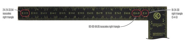
The first entry on the far left-hand side of the brace table indicates an isosceles right triangle with two sides that measure 24 (of any unit of measure) and a hypotenuse that measures 33.94 (in the same unit of measure). Each of the following 12 entries is the same triangle but with different dimensions. The final entry on the far right-hand side of the brace table is a basic 3-4-5 right triangle, in this case with sides measuring 18 and 24 and a diagonal of 30.
Working the triangles. The first 13 entries on the brace table are actually the same triangle. All are isosceles triangles, which means they have two equal sides. They also have the same angles, which are two 45-degree angles and one 90-degree angle. On every one of the entries, you can reduce the triangle to a 1-1-1.414 triangle by dividing all three sides by the smaller number in the entry.
The last entry on the brace table is 18-24-30. This is a 3-4-5 triangle multiplied by 6. The 3-4-5 triangle is easy to remember, and it fits the rectangular shape of a lot of building elements better than the 1-1-1.414 triangle.
These triangles can be expanded without changing any of the angles by multiplying the lengths of all three sides by the same number. If you multiply all three sides of the familiar 3-4-5 right triangle by the number 8, for example, you end up with a right triangle with sides of 24, 32, and 40. This enlarged triangle retains the exact same angles as the 3-4-5 triangle. This process, by the way, works in reverse: You can shrink any right triangle by dividing all three sides by the same number.
What’s more, you can use these numbers with any measuring unit you want. You might use a right triangle that has an altitude of 24 feet, a base of 32 feet, and a hypotenuse of 40 feet to square up the foundation of a house. Or you could use a right triangle with an altitude of 24 inches, a base of 32 inches, and a hypotenuse of 40 inches to square up a bookcase.
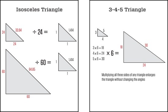
The ratio of the sides of an isosceles right triangle is 1-1-1.414 (left). Reducing the 24-24-33.94 triangle on the brace table by a factor of 24 and the 60-60-84.85 triangle by a factor of 60 produces identical 1-1-1.414 triangles. This pattern holds for all but the last 18-24-30 triangle on the brace table, which is a 3-4-5 right triangle (right). These ratios are commonly used in construction to determine that two layout lines are exactly perpendicular to each other.
Dealing with fractions. If you flip the square over and look closely at the numbers in the first two lines of the rafter table, you’ll see that they’re in decimal form. Although it’s not self-evident, the numbers in the brace table are also in decimal form. The reason these numbers are in decimals is because they are meant to be multiplied or divided.
These tables first appeared on steel squares almost two centuries ago, and for most of that time, carpenters have had to convert their fractional measurements into decimal equivalents in order to do the required math. There are many ways to make these conversions, and it wasn’t too hard to do before we had calculators. There are also a few tricks to avoid making these conversions, which I’ll explain below.
Foundation Layout
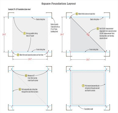
Once you’ve cracked the code, you can see that the first entry in the brace table describes a triangle that has two sides of 24 and a hypotenuse of 33.94. Here’s how to use this information to lay out a basic 24-by-24-foot foundation. Start by setting up two parallel strings 24 feet apart on batter boards, marking the first two corners on one line (the “front” string line in the illustration, below).
Next, use a long tape measure (I use my Crescent Lufkin HYT 100D 100‑foot engineer’s scale tape; see photo on below) to pull the 33.94-foot measurement diagonally across the layout to mark the third corner on the back string. After measuring and marking 24 feet down the back string, measure diagonally in both directions to double-check the layout. If the measurements are equal, the layout is square. Finally, preserve the layout by installing strings that represent the perpendicular walls.
Tip: When I first set string lines on batter boards, I use mason’s line blocks to hold the strings. This way, I can move the lines laterally as I make fine adjustments. After I’m satisfied with the layout, I attach screws to anchor the strings and preserve the layout.
Using an engineer’s scale. For the 24-foot square just described, the critical dimension is the 33.94-foot hypotenuse. You can convert the .94-foot dimension into 11 1/4 inches by multiplying .94 by 12 (this comes to 11.28 inches). But you don’t need to make this conversion mathematically if you have a tape measure marked with the engineer’s scale, where feet are divided into tenths and hundredths rather than inches; simply measure and mark the 33.94-foot dimension using a 100-foot engineer’s tape measure.
To lay out a perfectly square foundation with 90-degree corners, use the isosceles right triangle in the brace table that corresponds most closely to the desired dimensions, and set up batter boards and string lines as described in the steps above.
A tape measure laid out in the engineer’s scale is a great time-saving tool, but it is not compatible with inches—even if the inches are divided into tenths. This means that the tenths scale on the framing square should not be used to convert to the engineer’s scale. Here’s why. The engineer’s scale is divided into tenths of a foot, which are further divided into hundredths of a foot. A standard foot, on the other hand, is divided into 12 inches. If the inches are divided into tenths, there are 120 of these increments per foot. At 1/120 foot, these increments are smaller than the 1/100-foot increments in the engineer’s scale.
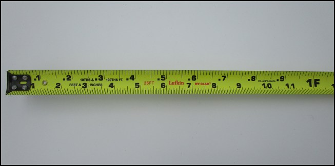
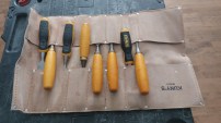
To lay out foundations, the author uses a tape measure marked with the engineer’s scale, which divides a foot into increments of 100 rather than inches. This tape also has a standard scale marked along the bottom edge.
Once in a while, though, you might want to convert from one scale to the other. If you use math, it’s a two-tiered process. To convert 5 3/4 inches to a decimal foot, for example, start by converting 5 3/4 inches to 5.75 inches, then divide 5.75 by 12 to get to the engineer’s scale equivalent, which is .48 foot. To go from hundredths of a foot to inches, multiply the decimal by 12. In this case, .48 x 12 = 5.76 (5 3/4 inches).
It’s simpler and easier, however, to measure and mark the length of the partial foot in one scale, then remeasure that distance with the other scale. For this reason, 6-foot engineer’s scale rulers have standard inches and fractions on one side and the engineer’s scale on the other. And engineer’s scale tape measures that are 25 to 30 feet long usually have standard feet and inches along one edge and the engineer’s scale along the other.
Laying out a 25-by-27-foot foundation. Of course, you won’t always be lucky enough to have a foundation that is exactly the same as one of the entries in the brace table. To lay out a 25-by-27-foot foundation, for example, you can take either of two approaches. In the first, you would simply lay out a 24-by-24-foot square as described above, then move two of the lines to enlarge the rectangle to 25 feet by 27 feet. This method would not require math at all (see the illustration, “Expanding the Rectangle,” below).
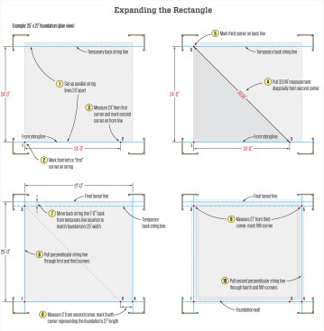
Once a square with 24-foot sides has been laid out as described above left in steps 1 through 5, it can be expanded into a 25-by-27-foot rectangle (or a rectangle of virtually any dimension) by following steps 6 through 10, above right. The key to this approach is the ability to take accurate measurements and mark them on the string lines without deflecting the strings.
The second method would require one multiplication equation to calculate the hypotenuse of a triangle with two 25-foot sides. I would probably choose this method because the math would only take a couple of minutes (less with a calculator). This would be a good trade-off for not having to move the line.
Back in 1976, a lot of carpenters knew that they could quickly find the diagonal of a square (or the hypotenuse of an isosceles right triangle) by multiplying the length of the side by 1.414. They committed this number to memory and used it often to square up their layouts. My sister, who is an avid quilter, has used the same formula to keep her quilts square for more than 40 years. To square up the 25-by-27-foot foundation mentioned above, for example, multiply 25 by 1.414 to find the hypotenuse of a triangle with two 25-foot sides, or 35.35 feet (see the illustration, “Expanding the Triangle,” below).
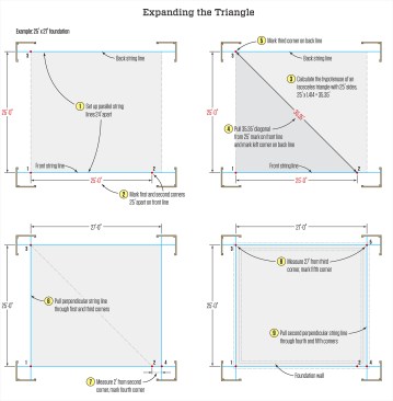
Another way to lay out a 25-by-27-foot foundation is by setting the initial parallel string lines 25 feet apart, then using the 1-1-1.414 ratio of an isosceles right triangle to calculate the length of the diagonal, or 25 x 1.414 = 35.35 (above left). After marking a square with 25-foot sides, extend one side of the square by 2 feet to create a 25-by-27-foot rectangle, as shown above right.
I still use this formula a lot because I can multiply 1.414 by 10 or by 100 in my head by simply moving the decimal point over one or two places. To create a 10-by-10-by-14.14-foot triangle, for example, just move the decimal over one place; to create a 100-by-100-by-141.4-foot triangle, move the decimal point two places to the right. With this triangle, you can use either inches or centimeters to create a triangle that fits a smaller layout.
The builder who laid out the foundation for my house in 1949 may have used the final 18-24-30 entry in the brace table for reference, because my house footprint is a rectangle measuring 34 feet wide and 56 feet long. To do this, he could have expanded the 3-4-5 triangle by a factor of 11, then laid out a 33-44-55 triangle. After establishing the perpendicular line, he could have moved the parallel line one foot (see illustration, below).
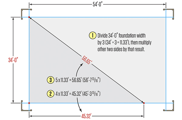
Or he could have divided 34 by 3 and then multiplied the result, 11.33, by 4 and 5. This would produce a 34-by-45.32-by-56.65-foot triangle. Doing it this way would have required less than five minutes of math, but he wouldn’t have had to move the line after he squared up the foundation.
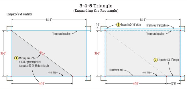
One way to lay out a 34-by-56-foot rectangular foundation is to multiply the sides of a 3-4-5 right triangle by 11 to create a 33‑44-55 right triangle, then expand the rectangle as shown.
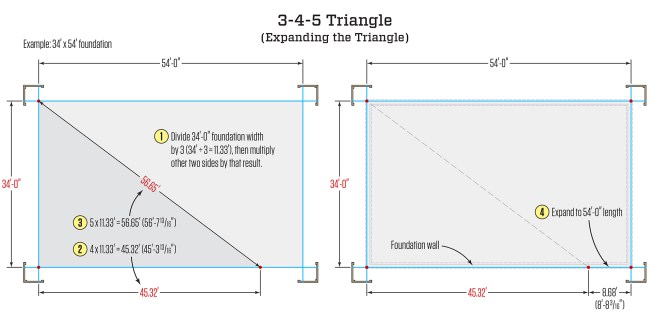
Alternatively, you can find the dimensions of a triangle with a height of 34 feet by dividing the height by 3 (34/3 = 11.33) and multiplying the other two sides by that result.
Illustrations by Tim Healey; photos by John Carroll and Andrew Wormer