by Jeff and John Tooley
It all begins at framing: The earlier in the process builders start thinking about air-sealing, the more energy-efficient, durable, and comfortable a home will be.
As building scientists working to improve the durability, comfort, and energy performance of homes, we spent years back in the 1980s trying to make houses more airtight. The initial efforts focused on things like sealing and caulking windows and weather-stripping doors. But that was before we realized it would be much more effective to focus first on the framing.
Our initial testing of house air leakage began by using blower-door equipment to map the air-pressure boundaries of houses. A blower door measures air leakage through the building envelope (a sandwich assembly of framing, air barrier, vapor barrier, and insulation materials that makes up the home’s walls, top-level ceilings, and floors), using a powerful fan mounted in an adjustable frame that fits tightly into an exterior door opening (Figure 1). The fan blows air into or out of the building. Sensors in the blower door measure the airflow through the fan and the air-pressure difference between inside and outside. This information is fed to a small computer, which uses it to estimate the building’s air leakage rate.
Figure 1. A blower door consists of a powerful fan that is temporarily sealed into an exterior doorway of a house. The fan blows air out of the house to create a slight pressure difference between inside and outside. House airtightness is determined by the amount of airflow that it takes to maintain a 50 Pascal depressurization of the house. The tighter the house, the less air that’s needed to exhaust in order to maintain the pressure.
This procedure helped us gain a better understanding of where houses leak air. Over the years, we’ve improved our evaluation. Now when we pressurize a house to 50 Pascals with a blower door, we insert probes through small drilled holes into walls or floors that we can’t see into, and we can compare the pressures within those assemblies to the pressures in the living space. If the interior is at 50 Pascals, the outdoors is at zero (or neutral), and the space inside a framed wall or ceiling is also at zero, then we know that the space within that wall or ceiling assembly is essentially outside the house. The instruments showed us that a lot of framed assemblies — like chimney or vent chases, drop ceilings, attic knee-walls, interior partition walls, or floor systems — tend to have big voids that communicate directly to the outdoor air. Floors or walls that we thought of as being inside the house were really more connected to the outside, and they were letting in the heat, cold, or humidity of the unconditioned outside air.
Caulking around the windows may seem important, but a large hole between the house and the attic is probably ten or a hundred times more critical. The example below (“A Room with a View, A Porch with a Problem”) — a beachfront house that suffered significant moisture damage because of air infiltration through a floor system connected to a porch roof — is only one of the many cases we’ve documented in which big air leaks through framed assemblies have caused a house to malfunction.
HIGH-PERFORMANCE FRAMING
Now that our investigations of existing homes have given us a good idea of where the major air leaks typically occur, the diagnostic equipment is less important. You don’t necessarily have to test each new house — just knowing where houses typically leak can help builders work more effectively.
The big concept. To build a high-performance house, the designer (or builder, if you’re doing the design work yourself) should call out on the plans the location of the air-pressure boundary for the house and the details that are required to maintain that boundary at various framing intersections.
First, the builder needs to make sure that the appropriate materials are on site during framing, and the framer has to address any potential gaps or disconnects in the conditioned envelope at the framing stage — such as installing solid blocking or solid sheet materials wherever they’re needed to complete the air-barrier assembly.
Second, in our experience, the insulation and air barrier should be in contact with each other at all times. This reduces the possibility of having air channels between the insulation and air barrier that may lead to convective losses.
Any holes for wiring, plumbing, vents, and so forth that get punched through that sandwich of air barrier, vapor barrier, and insulation materials should be carefully patched by whatever trade made the hole. We’ve found that if the three systems — vapor barrier, thermal boundary, and air barrier — aren’t installed in continuous contact with one another, and if their integrity is not preserved right through the end of the job, they don’t function nearly as well. Some areas, like plumbing chases, dropped soffits, chimney framing, and unlocked floor structures, can create places where the air barrier and the insulation are misaligned. When the thermal and air barriers are misaligned, the insulation is no longer insulation; it is a high-efficiency air filter. In addition, voids and gaps in the insulation can cause convective loss between the insulation, drywall, or sheathing that short-circuit the insulation. All of these thermal bypasses compromise the energy efficiency, durability, and comfort of the whole building.
Coastal conditions. These principles are even more important for homes in a coastal climate. On the coast, you’ve got the driving force of wind to contend with. Other forces that move air through houses, like the “stack effect” (the tendency of heated air to rise through the house on a cold day) or the room pressures created by air supply and return ducts, tend to operate intermittently when the equipment is operating or when the weather is very warm or very cold. But onshore and offshore winds can blow for weeks and months at a time — they’re a constant force in the coastal environment.
Besides the potential for condensation and moisture damage, the latent heating or cooling load (see Soundings, in this issue) caused by moisture-laden wind intrusion can waste significant amounts of energy. We’ve also seen fireplaces, furnaces, and water heaters back-draft just from the suction created inside leaky houses by wind passing over the house. All of those performance issues can be minimized when the house is framed to be airtight and penetrations are carefully sealed.
PLUGGING THE BIG HOLES
If houses were just simple boxes, it would be easy to define and detail the air barrier at the framing stage. Basic ranch houses don’t offer much trouble in this regard. But most houses these days have at least a few complex shapes that make a hole in one space and a bump into the adjoining space, and many houses are loaded up with that kind of element.
Here are a few of the top troublemakers:
• Chases for vents, fireplaces, or pipes
• Drop ceilings, coffered ceilings, and “tray” ceilings (Figure 3)
• Cantilevers where floor systems overhang walls or bay windows that project out
• Stairways, especially stairways that connect to attics
• Attics that connect to floor systems, such as a knee-wall attic in a story-and-a-half house or a porch attic that adjoins a floor system (see “A Room with a View; A Porch with a Problem,” below)
A quick look at a couple solutions to such problems will help you understand how to stop the air through these critical junctures at the framing stage:
Attic-to-cathedral transitions. Consider, for example, the changes in ceiling elevation in the house shown in Figure 2. The framer has used rigid sheet to face the backs of the vertical stud walls between the conditioned high-ceilinged space and the unconditioned attic adjacent to it. In one case he has used OSB; in the other he has applied Energy Brace, a heavy cardboard-like material with a foil or plastic facing from Ludlow Coated Products (www.ludlowcp.com). Energy Brace is a less expensive air barrier than OSB, and it is only about 1/8- to 1/4-inch thick, so it can be conveniently added to framed assemblies without significantly affecting their dimensions.
Figure 2. At left, the framer used OSB over vertical stud between the space below a cathedral ceiling (created with scissor trusses) and an unconditioned attic. In the same house, framers applied Energy Brace as a backing between living areas and the attic (bottom). In each case, the solid-sheet material provides a stable, airtight boundary around this home’s conditioned space that can be insulated to preserve the thermal barrier and air barrier at once.
These wall stud cavities can now be insulated and drywalled, and they’ll form a segment of the continuous, stable, airtight, and insulated boundary around this home’s conditioned space. Without the rigid materials applied during the framing phase, the insulator and drywaller might end up confused about how to detail this juncture — and it might end up without its insulation or without its air barrier, or without either one, as we have often seen.
Raised or lowered ceiling profiles. In Figure 3, we have two complex architectural ceiling details, framed in beneath a truss roof. On the right, a two-level soffit drops below the main ceiling plane, and on the left, an octagonal coffer, or tray, rises above the main ceiling plane. For the soffit, the framer has applied OSB to the bottom truss chord before framing in the detail beneath. For the octagon raised ceiling, the framer has applied OSB to the top of the extra framed element. In each case, the OSB will serve to isolate the occupied space beneath from the unconditioned attic above. The insulator now has simple flat planes to apply his attic insulation to, instead of having to puzzle over how to place it.
Two architectural ceilings framed beneath a truss roof have been backed with OSB. In each case, the OSB isolates the occupied space from the unconditioned attic, providing the insulation subcontractor with simple flat planes on which to apply his attic insulation, instead of forcing him to puzzle out how to fit insulation into complex cavities. TEAM APPROACH
Even the most complex framing elements can usually be dealt with in a similar manner. But the key is teamwork: the designer, the builder, and the framer have to be on the same page and stay in communication in order to accomplish these details at the most practical point in the construction sequence.
We feel not enough coastal builders have adopted the framing techniques outlined here. But the techniques are simple enough. The sooner builders start thinking about air-sealing at the framing stage, the sooner homes will start to be more energy-efficient, more durable, and more comfortable. ~
John Tooley Sr. is a building scientist with Advanced Energy Corp. in Raleigh, N.C.; Jeff Tooley owns and runs the Healthy Building Company, based in Siler City, N.C.
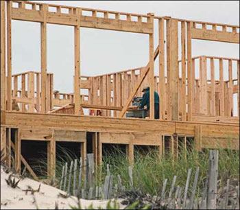
A Room with a View; A Porch with a ProblemThis North Carolina beachfront house (above) was damaged by moisture-laden wind driving in through the floor system at the framing juncture where the projecting room above the porch intersected the home’s second-floor frame. Continuous floor joists ran past the first-floor wall plate to form the porch ceiling, and wind easily flowed into the porch roof assembly, through the unblocked floor frame cavities under the small bump-out room, and into interior floor and wall framing voids (below left). Off-the-scale moisture readings were causing the tongue-and-groove pine paneling on the home’s interior to buckle and crack (below right). Defining a continuous air-pressure boundary on the plans at the edge of the conditioned space and building the air barrier in at the framing stage using solid blocking or panel products with caulked joints would have prevented this severe moisture damage (and saved energy to boot). |


