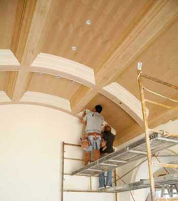
When my brother first told me about it, the job seemed like an over-the-top challenge: installing a coffered ceiling in a barrel vault. But after some thought, we realized we could use the same techniques we’ve used on radius balustrades and countless curved walls. With a router, a trammel arm, and plenty of patience, we figured, we could take it on.
Finding the Ceiling Radius
The plans called out a 134-inch radius for the barrel vault but didn’t specify whether the measurement was from the framing or the drywall. So our first step was to check the actual radius at the drywall. To do this, we placed a 6-foot level against the ceiling, then measured perpendicular from the center of the level up to the drywall. Using a Construction Master, we quickly found that the ceiling had a 129-inch radius on the face of the drywall.
Determining the Radius
Making a Mockup
We always make a mockup of coffered ceilings; it’s the best way to determine the exact size of the backing and the crown position, and for the client to visualize the finished product. In fact, we won’t proceed with an installation until the mockup has been approved.
On this job, the homeowner couldn’t decide between crown styles, so we assembled the mockup with two different types of upper crown molding. The client picked the most difficult option, of course — one with a crown that couldn’t be coped, as we discovered during installation.
Another issue was that the two-piece buildup, which had been designed by the architect on the project, didn’t allow any room for error, because the two pieces of crown butt each other to form one large profile. With no center fillet strip or soffit to hide inconsistencies, there would be no wiggle room. This meant we would have to cut the backing for the upper crown molding so that it followed the ceiling nearly perfectly.
Setting Up the Trammel Arm
Because every piece of backing had to be precise, cutting it with a jigsaw was out of the question. Instead, we used a trammel arm — a piece of 1×4 — attached to a router. There are many ways to attach the router; some carpenters make an auxiliary wooden base and screw the router right to the base. For this job, we used an adjustable fence made by Porter-Cable (42700 Edge Guide, $40 at Amazon.com). Since this guide doesn’t fit every brand of router, we had a local machine shop make an aluminum adapter so we could use it with our Bosch plunge routers. The nice thing about the Porter-Cable guide is you can quickly fine-tune the trammel-point distance.
Working from the drywall surface, we set up the three trammel points. The longest radius was for the top of the beam, the shortest for the bottom of the beam; a third intermediate point was for the bottom of the upper-crown backing. The trick, when setting up a trammel arm, is to make sure you’re measuring to the correct side of the router bit.
Installing Beams and Backing
We made the beam sides and the crown backing from 3/4-inch MDF. Rather than use the trammel arm to cut every piece, we made two templates — one for the side and one for the backing — and used them to duplicate the additional pieces. We found it fastest — and least dusty — to trace the pieces and make rough cuts with a circular saw and jigsaw, then clean up each piece with a top-bearing template bit.
After laying out the beams, we attached blocking to the ceiling with panel adhesive and nails. We waited a day for the adhesive to dry, then installed the sides of the beams, followed by the three-layered beam bottoms. We used 1/4-inch MDF for the first two layers, and 1/4-inch alder plywood for the exposed bottom layer.
Next we installed the upper crown backing, then moved on to the straight intersecting beams, repeating the process. To make sure the crown molding reveals would be dead on, we used gauge blocks at every step.
Installing the Crown
Each coffer had four pieces of straight hardwood crown (two lower, two upper) and four pieces of flexible plastic crown. Installation took a lot of patience. We ended up using a combination of coped ends and open miters to get it done.
Starting with the bottom crown, we first experimented with open miters. We found that cutting both pieces at 43 degrees got us close, but the joints didn’t close as tight as we wanted. We also tried coping the ends of the flexible crown, but still couldn’t get a good fit.
Finally, we tried coping the ends of the straight hardwood. Cutting the coped end at 43 degrees worked best. We cut the pieces a little long and pressed them into place. This locked the flex trim into position and hid the inconsistencies you always get between flexible molding and its hardwood equivalent. The tight copes hid everything.
Uncopable Crown
I thought we’d be able to cope the upper crown, too, and was looking forward to working on the smaller profile, but that molding turned out to be the biggest problem — it wasn’t copable. Whenever a crown molding profile turns to horizontal — whether it’s on a flat fillet, a bead, a bullnose, or a cove — the molding can’t be coped.
One good example is the bottom corner of most crown moldings: We’re all taught to cope that bottom fillet paper-thin, so it’s practically the thickness of the paint, and then to install the molding so that the paper-thin miter laps over the previous piece. Why? Because you can’t cope a profile that runs level.
We used test pieces to check the fit of the miters, marked the length of each piece with the miter squeezed tightly in place, glued both sides of every miter, then sprung each piece into place, nailing off the miters and leaving a bow in the center, which we fastened last.
Except for the coloration difference between the flex molding and the solid alder, the upper and lower crowns looked like a single piece when we were finished. And by the time the painter finished applying multiple veneer coats and graining, the whole ceiling looked like alder.
Gary Katz is a finish carpenter in Reseda, Calif., and the moderator of JLC Online’s finish-carpentry forum.