As a structural engineer, I get a steady stream of calls from remodeling contractors looking for ways to remove bearing walls and posts, either to enlarge a space or to create more headroom.
One such call came from the owners of the 1960s-era ranch shown here, which sat on a sloping lot with a full basement. The home’s construction was pretty typical: The 26-foot-long main girder in the basement ceiling was supported by two intermediate posts spaced about 8 feet apart. Our plan was to create a new 16-by-20-foot home theater and play area by removing one of the posts. But first I needed a way to reinforce or replace the existing four-member 2×10 girder that supported not only the first-floor joists but also a bearing wall that carried attic joists used for light storage.
Structural Options
The most obvious option — installing an engineered lumber or steel undergirder — wouldn’t work, because at 7 feet 8 inches the basement ceiling wasn’t high enough. Also, a quick calculation revealed that with only 9 1/4 inches of depth (2×10 floor joists) to work with, even the strongest engineered lumber wasn’t beefy enough to function as a flush beam.
Steel solution. We could have used an 8-inch wide-flange I-beam, but the labor and shoring necessary to support both the first floor and the attic during construction replacement would have been costly and disruptive to the client.
Instead, I looked for a different steel member that might be easier to install. I was originally thinking of a “C” shape when I started browsing the Steel Construction Manual (American Institute of Steel Construction, www.aisc.org), the best resource for steel design. Paging through, I remembered that a traditional I-beam could be cut down the center of the web, creating two T-shaped pieces of steel called wide-flange tees, or WTs. Thinking about the project at hand, I realized an important advantage of this approach: The WTs could support both the joists and the existing beam, which would eliminate the need to through-bolt the steel and built-up 2×10 girder.
There are no capacity tables for WT members in the beam section of the steel manual — as there are for the common structural-steel shapes — so designers have to use the shear, bending, and deflection tables to figure out the design calculations. After doing the math, I concluded that a pair of WT8x13 steel beams, made from a W16x26, could handle the load and would be relatively easy to install.
Making a WT Beam
The way that WT members are made — slitting a wide-flange I-beam down the center to produce two equal-sized sections — releases stresses in the steel, which can cause a slight arch.
My local welding shop cut a 20-foot-long W16x26 — a common beam size — into a pair of WT8x13s over the course of a day and a half, allowing the steel to rest between cuts in an attempt to reduce the camber. When the cuts were complete, the camber was in the correct direction and limited to about 3/4 inch. I figured the slight arch would reduce the dead-load sag created by the longer span.
Temporary Support
A couple of days before the steel was delivered to the site, the contractor built two temporary walls to support the joists during beam placement. Each stud wall was placed 36 inches off the beam centerline, providing a 6-foot working space. The existing beam was strong enough to temporarily support the wall and attic joists above without the post, but to be safe we had the homeowner temporarily remove the items stored in the attic.
With the floor system supported, the contractor cut a 3/4-inch channel between the joist ends and the beam, using a recip saw fitted with a demolition blade. Since the beam was only 8 inches tall, the top inch and a half of the 2x10s was left intact.
Preparing the Steel
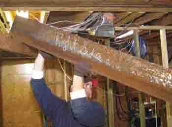
The two crew members on site used four-wheel dollies to move the beams, which weighed 210 pounds apiece. Each piece of steel would bear on the existing sill plate at one end and on a triple 2×4 post on the other. The stud post would replace the existing steel column and form part of a new partition wall.
Before we could place the steel, we had to notch the exterior sill plate to make room for the flange. But because we couldn’t easily notch the part of the sill underneath the existing 2×10 girder, we also had to notch the WT flange on one side of the web, which the steel fabricator did on site with a small torch.
Given that the flanges of a beam carry the bending forces, you might wonder how we could remove part of an I-beam’s flange without sacrificing the beam’s strength. Maximum bending stress in a simple-span beam (one with a support at each end and no intermediate supports) occurs at the center of the span — which is why you should never notch the top or bottom of a beam near the center of the span.
But at the ends of a beam, bending stress is zero, which makes it possible to trim the flanges of a steel beam — or notch a lumber joist — near the bearing points. (Again, this assumes a simple span. For continuous beams — those that span intermediate supports — or cantilevered beams, the shear and bending stresses are much more complicated, and cuts and notches should be avoided.)
Before cutting away the flange, I also needed to check that there would be enough of it left to spread the bearing over a sufficient area, so that the wood plate wouldn’t be crushed. After cutting it, we would be left with a 3-inch-by-5-inch bearing area, or 15 square inches.
On this project, we had SPF mudsills, which are rated for a maximum compressive force of 425 pounds per square inch; that means the 15 square inches of flange material would be able to transfer a load of 6,375 pounds (15 square inches x 425 pounds per square inch) before crushing the wood fibers.
Since there were two WT beams, this was plenty of capacity.
Placing the Steel
The steel was set on a drywall lift and hoisted into place a piece at a time. We marked and cut the wood post and secured it to the beam with Simpson A23 angles and self-drilling screws. We used Tapcons, driven at an angle, to attach it to the floor. The post would ultimately become part of a partition wall, so the connections were simply meant to prevent accidental bumps from dislodging it during the rest of the construction.
Installation of the beams took about six hours, including temporary shoring, cutting the joists, installing the steel, and removing the shoring. After the work was completed, I walked around the living area upstairs but couldn’t detect any noticeable bounce where the post had been removed. On paper, anyway, the floor was less stiff — but that wasn’t evident when walking around. And without a post in the way, the clients appreciate the new room below.
Jordan Truesdell, P.E., is a structural engineer in Blacksburg, Va.


