There’s nothing quite like a room with a full glass roof to capture the warmth of the sun. But all that overhead glazing can also collect a lot of condensed moisture when it’s cold outside and warm within. On sloped glazing, the water drips and stains the woodwork; in extreme cases, the sunroom environment also supports mold growth and wood rot. A glazing system that allows condensation to weep to the outside is critical to the long-term success of a custom sunroom.
Component System
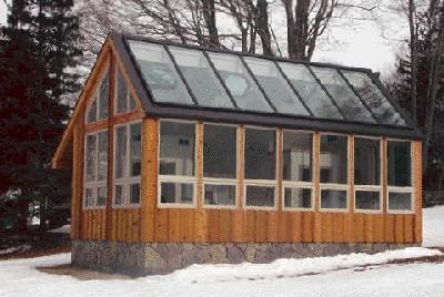
On a recent job, we built a custom, free- standing sunroom using Summit (Jeld-Wen, www.summitwindows.com) vinyl custom picture, awning, and trapezoidal units for the vertical glass, and three motorized Velux venting roof windows on the north-facing roof slope. Automatically controlled by thermostat and rain sensors, the roof windows allow cooler, fresh air to convect up from the low-mounted awning window vents. We also installed a separate, thermostatically activated power vent to further control indoor temperatures. For the array of 3×9-foot fixed glass panels on the south-facing side, we used Pro-Seal glazing bars (Abundant Energy, 800/426-4859, www.abundantenergyinc.com), a versatile glazing system for sloped and vertical applications. Pro-Seal’s glazing bars are made of extruded aluminum in a white or bronze finish and fit various glass thicknesses from 1/4-inch single-pane to 1-inch insulating glass. The bars come in 20-foot lengths, shipped by common carrier, or they can be factory-cut to lengths under 8 feet and shipped by overnight carrier. Since the components are field cut and installed, the shape of the glazing panels can be customized to suit eccentric or irregular openings. Panel size is limited only by the size of glass that can be manufactured.
The glazing bars come in various component profiles to make a complete system. On this job, we used perimeter extrusions on the top, bottom, and sides, and mullion profiles for the vertical divisions between glass panels. A bevel-topped purlin made for intermediate horizontal divisions is also available.
Each component of the assembly consists of four parts: a gasketed base, or bottom bar that rests against the framing and receives the glazing panel; a gasketed glazing cap that clamps over the glass; continuous EPDM (ethylene propylene diene monomer) rubber gasketing; and a trim cover to conceal and protect the clamping screws (see Figure 1). The perimeter glazing bar is available with or without a thermal break strip separating the inner and outer surfaces.
Figure 1.The Pro-Seal glazing system uses extruded aluminum profiles to clamp the insulated glass units between watertight rubber gaskets.
Structural Support
Pro-Seal is strictly a nonstructural, or “skin,” system and must be fastened to a wood or metal supporting frame. On this frame, we used 4×8 Parallam rafters, lag-bolted over an 8×16 structural Parallam ridge beam. While certain solid lumber species, such as Douglas fir or cedar, may be acceptable, stability is crucial. A wood frame that shrinks, twists, or allows excessive movement will spell big trouble for any glazing system. For this reason, pressure-treated lumber and green lumber are especially poor choices.
On the south-facing side of the building, which is fully glazed, we joined the wall corners and mullion posts to the roof framing with custom-welded 1/2-inch-thick steel moment connectors to resist wind racking. The north-facing walls and roof had conventional framing with enough sheathing to provide sufficient stiffness.
There are no rough openings in a custom sunroom; it’s finish work from the beginning. The upper edge of the sloped framing supports the glazing system and must therefore be as true and square as possible. Headers must be flush at the top with the rafters, and any bumps or crowns must be planed flat. Everything lays out on centerlines; the extruded aluminum bars are a consistent 2 1/2 inches wide and have full-length centerlines inscribed on them to help with alignment.
When we had completed the framing, we covered the rafter tops with a peel-and-stick membrane underlayment to prevent any possible condensation from contacting the wood (Figure 2). At the eaves, we installed custom-bent aluminum apron flashing that runs from the bottom edge of the roof opening over the edge of the roof.
Figure 2.As an extra precaution against condensation staining, the author lined the top edge of the rafter framing with a self-sticking rubberized asphalt membrane.


