I’ve worked as a mason for 31 years and have kept things interesting by taking on the most unconventional and technically challenging projects I can find, whether in repair, remodeling, or new construction. Recently I did a massive high-end residential job that fit that description well.
The project called for two gable-end reinforced masonry walls that would perform an unusual structural function: provide the support necessary to offset the centerlines of two large masonry chimney flues that traveled as far as 8 feet horizontally from the fireplaces they served. This unique arrangement allowed the chimneys to pass through the roof centered on the ridge. The floor and roof framing would also depend on the masonry for structural support, from both sides of the walls.
These functions would place the walls under not only vertical compression, which unreinforced masonry can handle in spades, but also lateral stresses, which it cannot. Another major concern was wind-loading, which took on added importance because of the walls’ size and height.
Regardless of its specific application, reinforcing a block wall to resist lateral and tensile stresses follows the same general, prescriptive steps, which I will cover in this article.
Winter Work
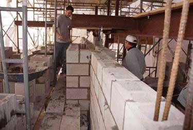
The blockwork was on the critical path; the floor and roof framing could not be completed without it in place. After we built one wall to the next floor height, we removed our scaffolding to allow floor framing to proceed. Meanwhile, we moved to work on the other gable. We started work in the middle of winter and ultimately performed about half of this job under winter conditions.
We began by staging both sides of the wall with pipe scaffold and enclosing the perimeter with translucent, fireproof tarps. (Regular poly sheeting, like the blue tarps used everywhere else and commonly used to enclose work areas, is highly flammable and poses a serious risk to workers. Back when I was an apprentice, I witnessed a blue poly tarp enclosure go up in a flash, ignited by an open-flame heater. The crew was fortunate not to have been inside at the time.)
We bridged the span between the staging with “putlogs” — steel scaffolding beams made for this purpose — then decked it over solid with planks, plywood, and more fireproof tarps. This temporary roof completely covered the work area and prevented the tarps from sagging under rain and snow loads. We kept the enclosed area comfortable with propane heaters, which run clean and are easy to maintain.
To protect the sand and cement — not to mention the laborers mixing the mortar and grout — from extremely cold weather, we also set up a heated mortar shack adjacent to the enclosure. Because the construction specifications prohibited all use of winter additives in the mortar and grout, we heated the sand and water prior to mixing. We used an electric-powered 400-pound-capacity Imer mixer (800/275-5463; www.imerusa.com) to eliminate the fumes otherwise produced by a gas-powered mixer. Thus set up, the masons worked through snowstorms and below-freezing temperatures in safety and comfort.
Building a Monolith
Block lay-up began at basement level over a poured concrete footing that measured 36 inches wide by 12 inches thick. Since the footing was placed by the foundation contractor over both undisturbed grade and compacted fill, it was reinforced with various sizes of horizontal rebar. We set L-shaped 18-by-36-inch #5 rebar ties every 16 inches o.c. to coincide with the block cells, connecting the block wall to the footing. The rebar became locked in later, when we grouted the block cells solid.
Concrete masonry unit (CMU) walls are relatively simple assemblies that rely on mortar to bond the blocks together and light-gauge welded wire that runs horizontally every other course to control the development of shrinkage cracks. A long run of masonry wall should also include a vertical expansion joint every 20 to 30 feet, to absorb the aggregate wall shrinkage and resultant cracking.
Solid grouting of block cells and steel rebar is normally used only in limited areas — vertically at building corners and at large wall openings, and horizontally in bond beams along the top of a wall. A bond beam helps tie the wall together as a structural unit and spread the floor or roof load evenly throughout the blockwork. This basic method creates a reinforced concrete “post-and-beam” framework that’s filled in with unreinforced hollow masonry units.
The basic expectation for a conventional, minimally reinforced CMU wall is that it will support a distributed load with redundant compressive strength. But such a wall has virtually zero tensile strength and therefore can’t resist lateral loads or serve as a shear wall. To perform as a shear wall, concrete masonry must be not only built as described above, but also systematically reinforced with steel rebar, with all cells fully grouted. That way, it becomes in effect a monolithic whole, similar to a reinforced cast wall.


