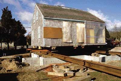
Even though I move buildings for a living, not every old house is worth saving. Once you factor in the expense of preparing a building for lifting or moving, and the cost of the actual lift itself, it may well make more sense to demolish and start new. But, fortunately for my business, there are also enough good reasons to salvage an older house. For example, in order to add a second story to an existing building, the builder must prove that the foundation can handle the added structural load. If the foundation fails on analysis, replacement is a common option, facilitated by raising the house. Then, there are older houses of good quality that are sold cheaply to be relocated to a new site. With some cosmetic repair and re-connection to utilities, these houses get a new lease on life. And, occasionally, a house is defined as a valuable antique and worthy of preservation, even if it means a delicate and expensive relocation. That was the case with a recent job we undertook moving the ancestral home of the Nickerson family, a classic Cape Cod house, across town and onto a new foundation. The house was not large, measuring 25 by 31 feet, with a small kitchen ell that could be cut away and moved separately. The main structure, however, had to remain intact. But it’s one thing to move a house built in 1972, where standardized construction makes the process predictable. This exemplary post-and-beam house was built in 1772, and there was nothing at all predictable about moving it. Nonetheless, it provides a good extreme case study.
Evaluating the Structure
One of the first steps in evaluating a building for lifting is to check the condition of the building’s underpinnings — the perimeter sill and floor joists. In this case, that meant hand-digging a few exploratory holes to inspect the framing over the marginal crawlspace foundation. The foundation was a double-wide course of locally made brick, laid about six high directly on grade. The stable, free-draining sandy soil on the site has to be credited with the exceptional condition of the oak sill and floor joists, which had only inches of clearance above the roughly leveled grade.
This was an unexpected piece of luck, as the rotfree framing would allow us to proceed conventionally by lifting from underneath the sills and floor system. Otherwise, contrary to preservation efforts, we’d have to destructively alter areas of the antique structure in order to lift the building by its walls.
Extreme LiftingIn 2003, we raised a large new house still under construction. The builder was blind-sided by a misinterpreted order of conditions for installing a foundation on a coastal dune. Coastal dunes are generally dynamic formations shaped by wind and waves and provide a natural line of defense against catastrophic beach erosion. Therefore, any proposed building on a coastal dune must conform to strict job-specific conservation regulations. Unfortunately, this project was well under way and tight to the weather when the stop-work order was issued. After long delays and legal wrangling, a solution was reached stipulating that the foundation must be modified to allow dune sand to drift naturally under and around a portion of the building. Instead of a continuous, solid wall, the foundation was to be replaced in part by regularly spaced wood pilings tied to existing helical footings. In addition, the building’s elevation was to be raised by about 2 1/2 feet. Of course, this revision turned out to be much easier said than done. We were forbidden to dig access holes around the foundation to insert the large steel I-beams needed for lifting under the sills. That meant that we had to work from inside the foundation instead, break through the floor at strategic locations, and lift the house by its walls using temporary, nailed-on ledger boards. It also meant that the I-beams would have to be fed in through existing door and window openings. The house measured 135 feet along its delta-shaped length, was 60 feet at its widest point, and incorporated a masonry fireplace and chimney that the builder and homeowner wanted to preserve intact. Not only that, but there were many expensive teak windows already installed that we’d have to take pains to protect from breakage. Ledgers nailed across studs (top) provided lifting points for steel beams, which were fed in through window openings (bottom left). Because coastal regs prohibited digging around the perimeter of the house, cribbing had to be stacked through the floor joists with the subflooring removed (bottom right). To make a long story short, we prepped the house for lifting from seventeen separate jacking locations (in contrast to the average of four to six), then I called on a colleague, Norman Messier of East Montpelier, Vt., to supplement my 6-jack machine with his 12-jack machine. After cautiously nudging up each jack in turn to test the system and listen for telltale structural creaks and groans, we raised them all in unison, ultimately lifting the structure almost 5 feet. The hydraulic gauges registered an aggregate load of 175 tons. Three weeks later, we lowered the building 2 1/2 feet onto the modified foundation without a single broken window or a crack in the chimney. I slept pretty well that night. — R.H. |
Although I determined that the building could be safely lifted, the owners, who planned to open it to the public as a fully functioning period-style home, didn’t want to proceed unless the original central brick chimney could also be lifted intact. This was a far dicier proposition. The chimney was actually made up of three back-to-back fireplaces with individual flues and an unusual beehive oven, all in fragile condition. I pulled out nearly 40 loose bricks, fallen from who knows where, simply by reaching up into the throats above the fireboxes.
There’s virtually no flexibility or forgiveness in a masonry structure, especially not one that’s stood for a couple hundred years. The owners sought an evaluation from masonry restoration specialist Richard Irons of Limerick, Maine. Irons declared the beehive oven exceptional and especially fit for restoration and further pointed out that, if demolished, it could not be recreated because its construction did not meet current code clearances and guidelines. With this encouragement, I had to decide on the best way to shore it up and lift it intact.
The building would be taken over the roads and had to clear tree limbs and power lines. Even without the masonry above the roofline, I’d be working with a 26-foot clearance height, including the 25-ton-capacity dolly wheels, something that must be considered when moving a building over the roads and under electrical utility lines. This part of the chimney was far too deteriorated and fragile to consider saving anyway, so we took it down to a point just below the ridge where it was bracketed by the roof framing. We saved all of the bricks for Irons’s later use in reconstruction. Underpinning the chimneys for lifting was the really tricky part. First, I had to determine what I had to work with.
Reinforcing the Chimney Mass
There’s nothing structural about the brick hearth or floor of the firebox, so we removed these bricks to expose the chimney underpinnings. As expected, there was no actual base pad; instead, the three flues rested on a platform of dry-laid field stones, set in sand. Behind the walls above the fireboxes we found more trouble in the old, crumbly mortar. Gravity alone was holding everything together.
To prevent the bricks from shaking apart during the move, we applied a sticky “skin” of rich masonry cement, reinforced with embedded chicken wire, to the fireboxes and brick above the lintels.
Simultaneously, we selectively removed field stones and earth from the sub-hearth area. With the foundations of all three fireplaces now somewhat exposed, we beamed a laser level from one firebox to the next and established a common, uniform level to work to. After spreading poly sheeting on the ground to prevent earth bonding, we reinforced the hearth area with 2-inch steel box tubing and rebar set on chairs, then filled the excavated area with a 4-inch-thick pour of 5,000-psi, site-batched concrete. We used a sand mix without stone aggregate to ensure good flow and penetration of the interstices between stones and bricks. I was hopeful that this temporary base would integrate the three chimneys and beehive oven sufficiently for the subsequent jacking operation. Before proceeding, we allowed the concrete to harden for about a week.


