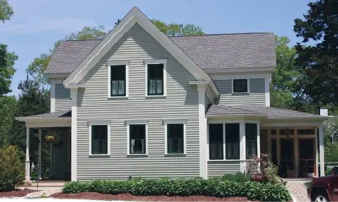
When my wife and I bought our 1850s farmhouse, it had none of the typical details I would expect to see on a home of the Greek Revival period — wide corner boards, built-out rakes, a heavy frieze, boxed cornice returns. So I set out to learn how to re-create those trim elements, using my place as a test case.
I started by studying my neighbors’ houses, then hit the bookstores and libraries. Although 18th- and 19th-century American builders borrowed many details from Greek and Roman architecture, construction references from the period are hard to come by. Probably the most helpful are the books by Asher Benjamin, who in the early 1800s wrote and illustrated several texts specifically for carpenters. His carefully drawn plates surely inspired many New England buildings, and they helped me better understand classical proportions and details.
Since practicing on my own house, my company has completed a number of projects in the Greek Revival style, both new construction and renovations. This article focuses on how we lay out and build the tricky cornice returns, using PVC trim instead of pine.
Simpler Details
Our most recent project was an overhaul of the Captain Loring House, circa 1850. Although the house’s original crown molding had the traditional ogee profile, much of it was in rough shape and some sections had been replaced with newer moldings that didn’t quite match. This was especially noticeable at outside corners, where various handymen had tried to cover up botched miter cuts with lead flashing and caulk.
The problem is that where a rake molding returns along a plumb-cut eaves fascia, as on a true Greek Revival, the molding gets narrower and the profile changes. Had we chosen to replicate the original ogee molding, we would have needed to order custom shaper knives to create the matching profiles. And because the house had several roof pitches, we would have needed a different set of cutters for every pitch.
I knew that this approach was too expensive; instead of a profiled crown, we would use flat stock with a 55-degree spring angle, as I had on previous jobs. The big advantage of a flat crown — besides the fact that it can be made from standard square-edged stock — is that there’s no profile to match at the corners.
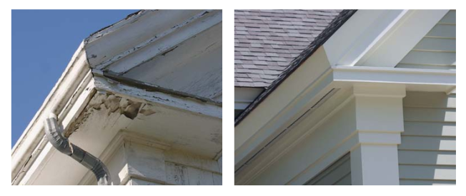
Considering its age, this mid-19thcentury Greek Revival cornice (far left) has held up well. Note the split fillet where the rake crown molding resolves into the profiled wood gutter along the eaves. At left, the author’s modern interpretation.
Scale Drawings
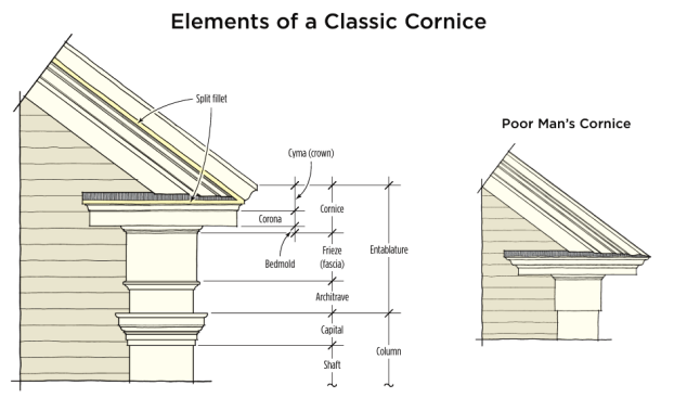
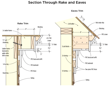
I began by drawing scale section views through the rake and eaves, taking the building’s existing 8-inch soffit as the starting dimension. The drawings gave me the sizes of the various pieces of PVC stock we would need, and helped us visualize how we would create the fillet — the square-edged piece at the base of the rake crown, which splits at the corner and runs horizontally along the eaves and back the other direction along the top of the cornice return. This is a key element of the true Greek Revival style — a detail we’d have to get right to mimic the original.
Full-Scale Mockup
Even with the section drawings, it was difficult to visualize the corner where the rake meets the eaves. I’m no math wizard, so I decided that we would work out the compound miters and other unknowns before going up on the roof.
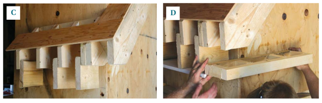
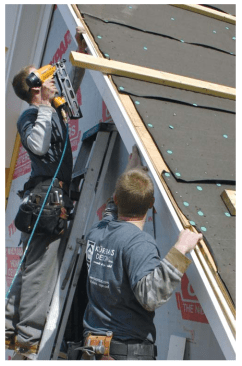
Using a mockup of a 12-pitch roof corner, lead carpenter Dave Crosbie first tacked pieces of the rake trim in place along the fly rafter, letting them run long at the bottom. Then, by butting pieces of the eaves trim against the rake trim, he was able to determine the exact point against the fascia where the mitered eaves crown meets the mitered rake crown.
Working down from that point, he established the elevation of the soffit, based on the dimensions on the drawing. He then attached jet blocks to the bottom of the rafter tails and projected this elevation back around the corner to establish the placement of the cornice return framing. Finally, he was able to easily establish the exact width of the narrower eaves crown and to determine the exact compound miter angles that would be required.
These compound cuts were anything but obvious, and changed with every roof pitch. Using mockups and trial and error, we eyeballed our way to some surprising angles. For a 12-pitch roof, for example, the eaves crown called for a 35-degree angle with a 48-degree bevel, while the rake crown board required a 10-degree reverse angle (meaning the long point of the cut is at the bottom of the crown) and a 48-degree bevel.
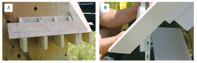
Using a mockup of a 12-over-12 roof (A), carpenter Dave Crosbie …
Top-Down Installation
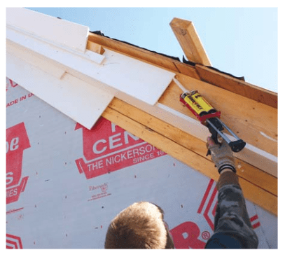
The first step in fitting the trim was framing the gable overhangs. We ripped the ladder stock from 2x8s, assembled the ladders on the ground, and installed them with TimberLok screws. For the PVC trim, we followed the same installation sequence we had used for the mockups, starting at the gable peak and working down to the eaves.
We glued the joints with Bond&Fill SlowCure, a sandable waterproof adhesive made for use with PVC trim. (Note: Bond&Fill is no longer made. Azek sells a slow curing trim adhesive; H.B. Fulller offers PVCTrimWelder. Both brands are available in slow cure as well as fast cure formulations.)
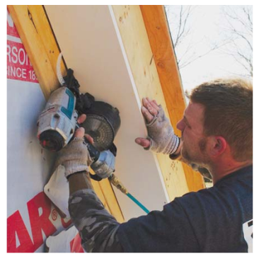
At the eaves, we temporarily tacked the fascia and crown in place, letting them run long so we could establish the eaves soffit line. We then framed the eaves soffits, using jet blocks, just as we had done with the mockup.
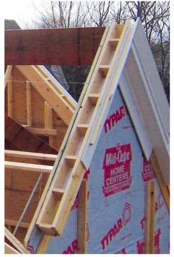
Overhang ladders ripped from 2x8s attach to the gable with Timb…
Bird Box
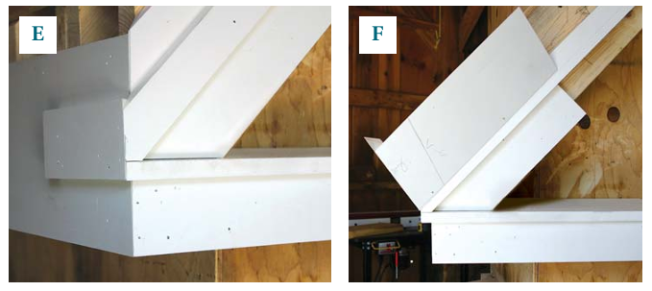
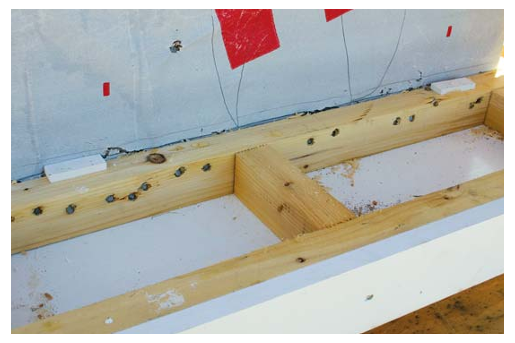
Once the soffit elevation was established, we could frame the cornice return, a distinctive feature of this trim style that seems to go by many names; Dave calls it the “bird box.” The length of the box is somewhat arbitrary — whatever looks “right” relative to the rake and frieze above and the corner board below it. The frieze elements under the eaves wrap around the top of the corner board and return to the wall below the cornice, suggesting a column capital.
Once the eaves framing and bird box were in place, we installed the PVC soffit boards on the eaves and the box, followed by the face trim and cornice top. We ripped the top of the cornice from a piece of 1×12, installing it with just enough slope to allow for runoff.
We then installed the bottom section of the rake soffit board, which we fitted to the sloped angle of the cornice top, sealing the joint with Bond&Fill. The rake frieze lands on top of the cornice, over a piece of lead flashing.
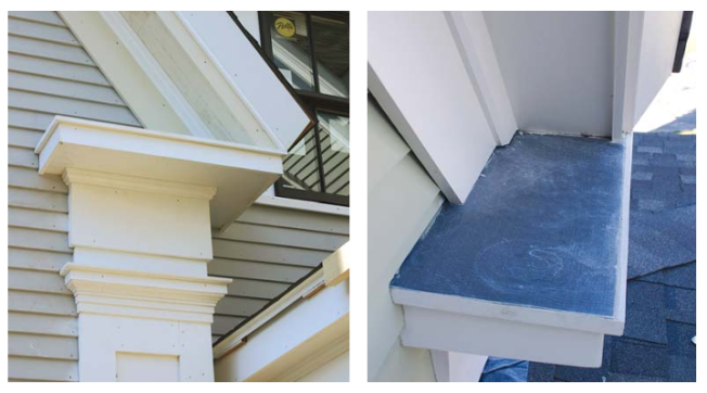
The eaves frieze wraps the corner and works in conjunction with the cornice to create the illusion of a capital over the corner board “column” (left). Lead flashing caps the cornice, and the rake frieze dies on top (right).
The flat crown extends the edge of the roof considerably forward of the rafter tails, so we added triangular nailing blocks behind it and brought the roof sheathing to its back edge. The roofing was an architectural-grade asphalt shingle, but instead of applying a metal drip edge, we used pressure-treated red cedar shingles so as not to detract from the crown.


