Radon is an odorless and colorless radioactive gas that forms during the decay of radium 226, an element found in varying concentrations in some soils and bedrock. It’s a health hazard, because prolonged exposure to it can lead to an increased risk of lung cancer. No one really knows how many people get cancer from this each year, but the EPA estimates that somewhere between 5,000 and 20,000 lung cancer deaths in the U.S. can be attributed to radon exposure annually. Fortunately, most home radon problems can be corrected fairly easily. In the seven years I’ve been performing radon mitigations in New Hampshire and Vermont, I’ve never encountered a problem I couldn’t fix. In most cases, dealing with the problem costs only $1,000 or so — a cheap price, all things considered.
Where Does Radon Come From?
In outdoor locations, radon leaks out in small amounts and is harmlessly diluted by the air. But if you build a house on a site that contains radon in the soil or bedrock, trouble can start. First, digging a foundation can open pathways that make it easier for the radon to reach the surface; blasting ledge, in particular, can open fissures that let out a lot of radon. Second, when you build a house on such a site, the radon tends to become concentrated indoors, rather than being diluted by the outdoor air. This is worsened by the slight negative pressure that exists in many homes as a result of fuel-burning appliances, ventilation fans, and the natural stack effect. This tends to draw radon from the ground through floor drains, pipe penetrations, and small cracks in the walls or slab. Radon levels are measured in picocuries per liter, abbreviated pCi/L. The recommended action level is an annual average of 4 pCi/L or more. Some homeowners perform a radon test on their new or existing homes, but 90% of my business is associated with homes that are changing hands. That’s because real estate agents in the two states where I operate are required to have buyers sign a waiver if they elect not to have a radon test done. Practically all buyers choose to have the test done (the cost is typically less than $100 and ordinarily comes out of the seller’s pocket). If the numbers come back high, I’m usually called in.
Depressurizing the Sub-Slab
Sealing cracks and other entry points may reduce radon levels somewhat, but it’s virtually impossible to solve the problem by sealing alone. The most successful approach is usually to embed one or more vent pipes beneath the slab and connect them to a vertical pipe that vents the radon to the outdoors. In many cases, a sub-slab ventilation system can be completely passive, like a plumbing vent stack. If the slab was poured over a uniform 4- to 6-inch layer of crushed stone or some other permeable material, and the vent stack is located inside, in a heated space, the natural stack effect often produces enough vacuum to vent the sub-slab adequately.
Active systems. If natural ventilation isn’t sufficient, it becomes necessary to add an in-line fan, typically in the attic, to increase the suction. Depending on the situation, in-line fans can have a capacity of anywhere from 90 to 150 cfm. Because a radon reduction fan must operate 24 hours a day, 7 days a week, only a high-quality fan designed for the purpose should be used. Systems that make use of a vent stack outside the heated envelope of the house — usually because there’s no good place to conceal it inside — always require a fan.
Radon ready. We encourage anyone who is building a new home to install a central vent stack in an interior partition wall and cap it in the attic. That costs next to nothing if it’s done at the concrete work and framing stage, but it saves a lot of trouble if the house later turns out to have high radon levels. It’s easy to activate the system by cutting an opening in the roof, extending the pipe, and sealing the penetration with a neoprene boot. (If that doesn’t provide adequate venting, adding an in-line fan in the attic will.) In practice, though, no one takes the trouble to do this, which means that I almost always have to find a way to retrofit one.
A Case in Point
The project photographed here involved a beautifully finished 4,000-square-foot house on a steeply sloping site with dramatic views of nearby mountains. Preparing the site had involved considerable blasting to clear a driveway and level the foundation, which may have contributed to an initial radon level of 17 pCi/L. That number wasn’t especially high, but I was concerned about the fill beneath the slab, which the builder told us consisted of a compacted layer of sand overlying broken shale from the blasting. The problem is that compacted sand — especially if it’s damp — is so dense that it’s difficult to draw much air through it, even with a very powerful fan. My job would be much easier if foundation contractors would pour slabs over a 4- to 6-inch layer of 3/4- to 1 1/2-inch crushed stone. Although the stone costs more than sand, it’s self-compacting, which saves the labor needed to compact 2-inch lifts of sand. Radon infiltration is also reduced if the concrete guys leave the poly vapor barrier under the slab intact, rather than slashing holes in it to reduce the amount of bleed water and speed finishing. To make things even more interesting in this case, the partial basement was finished as a recreation area, and radiant heat coils embedded in the slab limited the number of places we could safely drill through the concrete. Finally, the open-plan living space above left nowhere to hide an indoor ventilation stack.
Installing the Pipe
Our first step was to cement a special check valve into the floor drain and seal visible cracks in the floor slab (see Figure 1). Although that won’t solve the radon problem in itself, it’s necessary to prevent the vent pipe embedded in the slab from sucking air through such openings, effectively short-circuiting the whole system.
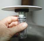
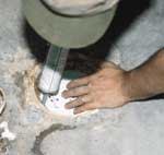
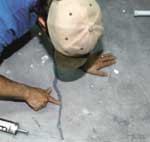
Figure 1. A special check valve is used to prevent the sub-slab ventilation system from sucking indoor air through the floor drain. It opens for drainage when weighted down by accumulated water, but when the drain is dry, a spring-loaded ball provides a seal that maintains negative pressure beneath the slab (top). Once the valve has been cemented in place (center), any visible cracks in the slab or foundation walls are repaired with a durable sealant (bottom).
Creating a vent sump. Fortunately, the builder had provided us with photos of the sub-slab taken just before the pour. The photographic coverage wasn’t complete, but we could see that one out-of-the-way corner of the utility room was free of rebar, radiant pipe, and other obstructions. Using a rotary hammer, we punched a 6-inch opening in the slab before cutting through the extruded polystyrene insulation beneath (Figure 2).
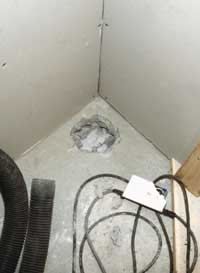
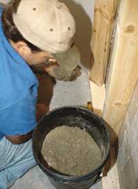
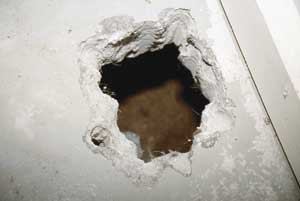
Figure 2. Once a vent opening through the slab has been made with a rotary hammer ( top), the fill beneath is dug out to create a sump (center). The finished sump is about a foot deep and as wide as a worker can reach by hand (bottom).
That made it possible to dig a cavity in the sand beneath — partly by hand and partly with the aid of a shop vac — to provide a sump for the bottom of the vent pipe. After cementing the 3-inch PVC vent pipe in place with hydraulic cement, we were ready to cut a hole through the adjoining partition wall and extend the vent horizontally along the corner of the ceiling and out through the exterior band joist (Figure 3).
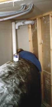
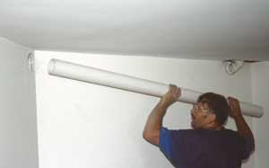
Figure 3. A length of 3-inch PVC — the lower end of which will be cemented into the slab — turns to pass through a partition wall (top). The sanitary tee will accept a second vent pipe leading to the garage. Above, the main vent line continues through a finished portion of the basement (later enclosed in a pipe chase) before exiting through an opening in the band joist. Like plumbing vent pipe, radon venting must be pitched enough to allow condensate and rainwater to drain.
Adding a secondary vent. With a straightforward floor plan, a single slab vent is usually enough to do the job. In this case, though, the built-in garage was supported by its own continuous strip footing, effectively isolating that section of the sub-slab from the finished area served by the initial sump. (Radon isn’t ordinarily a concern in a single-story garage, but if there’s living space above — as there was here — the area must be treated.) To deal with that, we created an additional sump in the garage floor and connected it back to the main vent stack with a long run of 2-inch PVC (Figure 4).
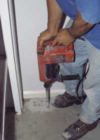
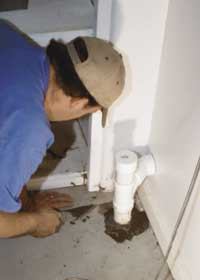
Figure 4. A second hole was hammered into the garage slab to create an additional vent sump (top). The vertical pipe was cemented in place with its open end extending just beneath the underside of the slab, minimizing the risk of blockage by an unexpectedly high water table (above). The uncemented cap on the vent line allows for later expansion, if needed.
Fortunately, we managed to route the pipe through a closet, under a flight of stairs, behind a bathtub in the downstairs bathroom, and back into the utility room, keeping it out of view and making life easier for the finish carpenter. To make sure that some future plumber doesn’t connect a sink drain to the radon-reduction system, the piping is identified with stickers (Figure 5).
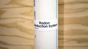
Figure 5. The radon-reduction piping is clearly marked at regular intervals to ensure that it won't be confused with plumbing drains.
Vent Stack and Fan
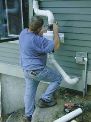
With the inside piping done, we connected the vent pipe to the fan and ran it up the exterior wall and through the gable-end overhang (Figure 6). Purely by chance, an existing weatherproof outlet was perfectly positioned to bring power to the fan motor. After we finished up, the builder’s carpenter built an enclosure around the fan and boxed in the exposed pipes.
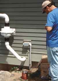
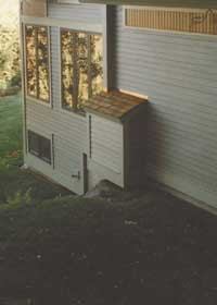
Figure 6. External vents always require a fan to provide a reliable draft. The vent pipe was secured to the fan housing with standard neoprene plumbing connectors before continuing up the wall of the house (left). The finished assembly — located on an inconspicuous outside elevation — was later boxed in for a more finished appearance (right).
Evaluating the Completed System
Before switching on the fan for the first time, we attach a U-tube manometer to an easily visible location on the vent pipe so we can confirm that we’re getting the required vacuum. In this case, we found that the system was pulling 1 1/8 inches of water, which translates to about 80 cfm (Figure 7).
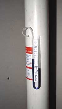
Figure 7. A vacuum monitor installed in the vent pipe confirms that the fan is providing the required negative pressure, although further testing is needed to determine whether indoor radon levels have actually declined.
Where’s the air coming from? That was quite a strong airflow, but a single vacuum reading tells relatively little about how well the system is operating. Without investigating further, there’s no way to know whether it’s depressurizing the sub-slab — as it should be — or drawing the entire volume of air through one or two concealed pathways near the vent sump. To rule out the latter, our usual approach is to drill a small hole in the corner of the slab farthest from the sump and install a second vacuum gauge. A solid reading there as well strongly suggests that the entire sub-slab is under negative pressure. At that point, we remove the second gauge, patch the hole, and prepare to test the post-remediation radon level to be sure it’s been reduced to a safe level.
Final test. In this case, though, the radiant heat coils in the slab prompted us to skip that step, because we didn’t want to risk puncturing the tubing. Instead, we went directly to the final test, which involves setting up a pair of electronic monitoring devices, each of which prints out a record of the current radon level once every hour (Figure 8). If the numbers we came up with were still too high, we’d have to bore additional holes in the slab and add additional vent pipes to bring them down.
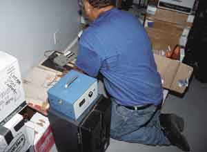
Figure 8. An electronic radon-monitoring device continually tests the amount of gas present. Once each hour, it prints out the current radon level as well as an average that factors in all previous readings.
But four days later, when we evaluated the printouts (Figure 9), we found that both machines had recorded levels far below the 4 pCi/L action level. (One recorded a four-day average of .2 pCi/L, while the other, some distance away, showed .5 pCi/L.)

Figure 9. After four days of continuous testing with two separate monitors, the highest average recorded came out at .5 pCi/L — comfortably below the 4 pCi/L action level.
While those figures may fluctuate slightly over time — they may rise slightly when the house is closed up tight during the winter months, for example — they’d never approach the action level, let alone the much higher levels seen originally.
For Further InformationEPA/625/2-91/032, Radon Resistant Construction Techniques for New Residential Construction, U.S. Environmental Protection Agency, 800/490-9198. |


