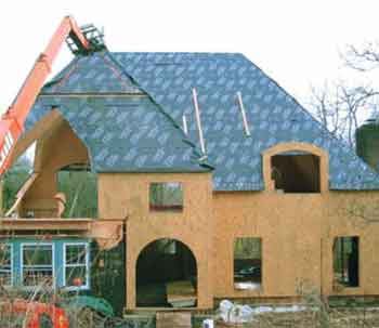
After 30 years of remodeling, I figured I had done just about everything there was to do — until I took on my first structural insulated panel (SIP) renovation. The project involved using SIPs to transform a modest cape into a country French-style home, with a roof featuring numerous irregular hips, turrets, steep pitches, and radius-top dormers.
Original estimates for stick framing the roof ran as much as $80,000 higher than the SIPs plan presented to the owners by project architect Bill Chaleff, of Water Mill, N.Y. Chaleff designs exclusively with SIPs and takes advantage of their structural characteristics — their ability to act as diaphragms, for example, or large flat beams. This means that roof loads are evenly distributed to the walls below, so that the complexities associated with stick-framing — structural ridges, hips, and valleys, and the point loads created beneath them — can be avoided. A SIPs roof goes together like a series of large planes (see Figure 1). For this project, Chaleff used SIPs from Insulspan (517/486-4844, www.insulspan.com).
Rebuilding the Walls
The cape — which was built in the 1930s — had already been remodeled three times. Because the first-floor deck wasn’t level, Chaleff sized the wall panels 3/4 inch short. This gave us room to shim the top of each one, so that the second-story subfloor would be level. Our benchmark was the ledger for the second-floor framing, which was attached to the first SIP wall section that we installed — the 14-foot balloon wall at the front of the house. From there we calculated the different top-plate heights, using various combinations of 3/8-inch through 3/4-inch plywood to ensure that the entire second floor came out level.
It took a three-man crew about three days to tack the first-floor wall panels into position. While this crew moved on to the roof, I brought in a few more crew members to secure the wall panels, which involved screwing the panels to the bottom plates on the deck and screwing the plywood splines at the joints. To prevent air infiltration where the panels butt, Insulspan SIPs have a small channel on the edge that must be filled with spray foam; we drilled holes along the joints at 8 inches on-center, then injected a two-part polyurethane — Dow’s Froth-Pak 180 — into the channels.
Once all the first-floor wall panels were secured, a boom truck delivered the steel beams that would support the second floor. We framed the second-floor deck primarily with wood I-joists, though we used some SIPs wherever there was exterior exposure below.
The second-story floor joists are attached to the SIPs walls with top-mount joist hangers, hung from either a ledger fastened to the walls or the blocking at the top of each panel. We attached the ledger with four 2-inch-long #10 screws and washers 12 inches on-center, plus construction adhesive, as specified in the plans. The connection has to be strong enough to not only carry the floor loads, but also allow the floor diaphragm to resist lateral thrust from the roof.
Installing the Roof Panels
Stick framing can always be adjusted when sections of a building don’t align perfectly. SIPs are less forgiving, however, and the complexity of this roof allowed practically no room for error. If my layout was off by as much as 1/2 inch, the hips wouldn’t come together, the dormers wouldn’t fit, and the turrets would be a nightmare to install.
Layout. We had snapped lines on the first-floor deck to help us lay out the wall plates. We wouldn’t be able to accurately locate the roof panels and turrets that spanned the two floors unless these lines were perfectly aligned with new lines on the second-floor deck. To do this, we projected points along the lower lines to the underside of the second-floor subfloor with a Stabila LaserBob, drove nails up through the plywood to locate these points on the second-floor deck, and then snapped new control lines to work from.
Assembling the panels. To assist in setting the roof panels, we had a 42-foot extending-boom all-terrain forklift delivered and ready to go when the two tractor-trailer loads of SIPs arrived.
The roof panels arrived with bevel cuts at the ridges and plates. The foam cores were routed for blocking, which we ripped from 1 1/4-inch-thick OSB rim-board stock and installed with screws and adhesive. This was labor-intensive work; in hindsight, having it done at the factory would have saved time and materials.
Working off a set of sawhorses made from 24-foot-long LVLs, we assembled each roof plane on the ground. To keep the project as dry as possible (and to avoid having to staple paper on a steep 18/12-pitch roof), we installed Tri-Flex synthetic roofing underlayment before hoisting the sections.
Fitting the roof sections. Assembled SIPs are incredibly strong; Chaleff estimates that more than 90 percent of the load transfers across the joints, turning each panel assembly into a huge box beam. We didn’t have to use any bracing when lifting the sections with the forklift. Locating the lifting point in the upper third of each one made it easier to drop the lower end onto the beveled top plates. We used tag lines to control the lift, and chain to prevent the lifting straps from slipping off the forks. The straps had a 5,000-pound rating; two of them provided plenty of capacity for lifting the panels.
The first roof section was the trickiest. We fastened it to the top wall plate with adhesive sealant and 10-inch-long structural screws 6 inches on-center — a connection strong enough that it requires no additional straps or hurricane clips.
After driving in the screws at the base, we braced the panel and also strapped it down to the deck to prevent wind from lifting it. We then rigged and set the opposing section, applying adhesive to the ridge blocking and fastening the ridge together with 3-inch-long #10 screws 6 inches on-center.
Once the main roof sections were fastened together, it was easier to install the adjoining large and small hips.
Because the panels were so accurately cut, we had to modify only one roof section — by cutting 1 inch off the edge of a panel connecting two hip sections.
After the roof sections were assembled, we foamed all of the spline connections (like the walls), working from the inside. Then we applied an adhesive vapor-barrier sealing tape supplied by the manufacturer to all the seams and the underside of the ridge to prevent warm, moist air from migrating into these critical joints and condensing.
Turrets and Dormers
We preassembled the turrets on the ground before placing them with the forklift (Figure 6). Like the flat roof sections, all of the connections were made using adhesives and an assortment of 6- to 14-inch-long special SIP screws and washers.
The radius-roofed dormers came assembled from the factory; we simply lifted them off the back of the flatbed and dropped them into place.
Even with all the extensive planning, we overlooked one thing: I was admiring a newly assembled SIP turret sitting in the driveway when I realized it wouldn’t fit under the power line running across the front of the property. Rather than wait for the line to be lowered, we drove the turret around the property via the street, where the lines were higher. It was quite a sight for the neighbors to watch a roof drive by.
Roof assembly (not counting the time spent building the curved rafter tails) took about three weeks. I estimate that, for the same price, we could have framed a similar roof — but I would have needed more skilled carpenters (only two were available for this job), the project would have taken a little longer to finish, and we still would have had to insulate the roof.
Mike Sloggatt is a remodeling contractor in Levittown, N.Y.


