Whether you call them deck piers, caissons, footings, or something else, as far as the International Building Code is concerned they are all essentially the same: isolated foundation systems that have to transfer loads imposed from above to the earth below. Being isolated means they don’t gain lateral stability from connection to the rest of the system (the adjacent piers). In other words, each performs alone and relies only on the surrounding soil for stability. Deck loads are usually minimal, so in deck foundation design, there are only a few things to consider, and the IRC provides guidance for most of them.
-
Deck and Railing Skills Workbook
No one can afford a deck failure. Focus your crews on safe and durable deck building with JLC’s Deck and Railing Skills Workbook.
Transfer of Load
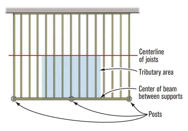
It’s fairly simple to determine the bearing area at the bottom of a foundation required to transfer loads to the earth. First, the tributary load on each post must be calculated. This equals the area of the deck that’s supported by the post multiplied by the combined design live and dead load (40 psf and 10 psf, in most cases). The area supported by the post is found by dividing in half the joist and beam spans on all sides of the post (Figure 1). For large decks with multiple beam spans, the loading for each post may be significantly different; a center post in a long beam will usually carry twice the load of a corner post. For simplicity, a builder will often make all the piers identical, sized for the largest load.

Figure 1. Determine the tributary area on a footing by measuring half the beam and joist spans on each side of its post. Include all of any cantilever. Multiplying these dimensions provides the square footage of the tributary area, and multiplying the square footage by the design load (typically 50 psf) yields the tributary load.
Once the load supported by each pier is determined, the next item to consider is the soil. The IRC provides a table for the compressive strength of various soil types, but it’s not much help unless you know the difference between silty sand and sandy silt (2,000 or 1,500 psf respectively). Expect 1,500 psf to be the default value in most jurisdictions (though I know that many allow more like 3,000 psf for decks). Dividing 1,500 pounds by a design load of 50 psf shows that a 1-square-foot bearing area (size of pier) can easily support 30 square feet of deck. Since most piers aren’t square, but rather round, remember you’ll need to find the area of a circle (pi times the radius squared, or for easier job-site math, approximately three-fourths of the area of a square whose sides are the same length as the circle’s diameter).
Depth of Foundation
The IRC requires that all foundations be placed a minimum of 12 inches below grade on undisturbed soil. This depth provides a minimal amount of lateral stability to the foundation, and the requirement for bearing on undisturbed soil provides assurance that the compressive load resistance expected of the soil type can indeed be achieved. Soil that has been removed and replaced, like foundation backfill, cannot be expected to perform as the same soil type in a natural state.
Beyond that minimum depth requirement, there may also be a requirement for frost protection of the foundation, established by the local building department. For freestanding decks, no protection is required; for all others, foundations may need to be as deep as 48 inches, or perhaps even deeper.
Design of Foundation
There are a few ways that a foundation system for a deck can be constructed and I’ll highlight three of them: footing, pier, and pier/footing.
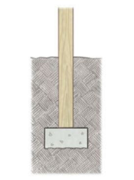
Figure 2. A basic footing is just concrete in a hole that gets backfilled, supporting a post. The concrete must be at least as thick as the greatest distance from the edge of the post to the edge of the footing
Footing. A footing foundation is relatively simple and is typically used where the footing doesn’t need to go below frost depth. This type of foundation is little more than a hole with a blob of concrete filling it (Figure 2). The horizontal area at the bottom of the hole is the bearing area and thus the size of the hole will be based on the load and soil type as previously discussed.<
The required thickness of the concrete (depth) will depend on the size of the post that will bear on the foundation and the bearing area. The thickness of the footing cannot be less than the greatest horizontal distance from the edge of the post to the edge of the footing. This assures that the 45-degree bearing cone that extends downward from the edge of the post will terminate at the side of the footing, not the bottom.
When a frost depth is required, a footing foundation can still be used at the bottom of the excavation and a preservative-treated wood post can then be placed below grade on top of the footing. Unless uplift resistance is an issue, the soil adjacent the post is usually considered sufficient to resist lateral movement. Otherwise, use of a hardware connection, perhaps coated entirely in waterproofing, can add a little assurance that the post won’t shift from the footing.
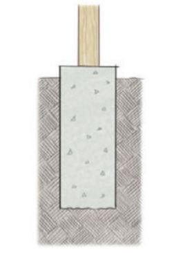
Figure 3. A pier foundation is similar to a basic footing, except it runs to above grade.
Pier. Another foundation method for decks is a pier (Figure 3). A pier works just like a footing, but it’s a lot taller and extends from the base of the excavation all the way to the top of grade. Unlike footings, pier foundations also generate load resistance from skin friction, the friction between the edges of the pier and the adjacent soil. However, without engineering and piers that are much deeper than those usually used on decks, you cannot take any credit for this resistance using the IRC.
When a large bearing area is required, using a pier foundation can result in an unsightly amount of exposed concrete at the surface, not to mention the excessive amount of concrete necessary to fill the hole. A 14-inch-diameter pier 36 inches deep is not fun to pour with bagged concrete mix. Commercial forms are available to cast a belled pier to handle these issues. In stable soils, it may be possible to dig the footing hole in a bell shape, which would save the expense of a special form. For these piers, detailed in the IBC, a maximum 30-degree angle from vertical can be used.
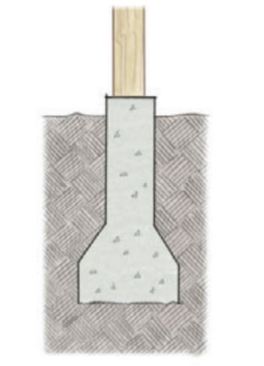
Figure 4. Belled footings are formed either by widening the bottom of the hole as you dig or by using a commercially available form.
Pier/footing. For what is called a pier/footing foundation, the bearing area is excavated to the required depth of the foundation (Figure 4). The form creates a footing of the required size at the bottom, followed by a narrower pier above, which runs to grade. Just as when a post bears on the top of a footing, so must the footing be thick enough to accommodate the 45-degree bearing plane of the pier. For upper-level decks, where the pier is likely exposed in the backyard landscaping, this type of foundation works well. Large loads are supported by what look like very small piers. For decks with a roof covering, this type of foundation also provides some uplift resistance, though it’s the job of an engineer to determine how much.
You don’t need to use a special form for a pier/footing. You can pour the footing to its required thickness, set a cardboard form tube on top of the wet concrete, and backfill around the tube as you fill it with concrete. Place only enough earth around the tube and on top of the footing as required to hold down the concrete footing as the weight of the pier increases. Once cured completely, the remainder of the excavation can be backfilled and compacted in 6-inch thicknesses. Too wet a concrete mixture will make this method difficult.
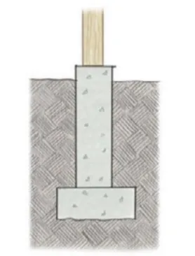
Figure 5. When larger loads dictate a large footing diameter, a pier/footing – a footing of the required thickness topped with a narrower concrete pier – is used instead of a large-diameter concrete column extending to grade.
Another method is to pour the footings first and the pier second (Figure 5). Though plain concrete foundations (no rebar) are allowed for deck construction, I recommended using rebar to connect the footing to the pier at the cold seam. By constructing in two pours, placement and compaction of the backfill over the footing is much easier.
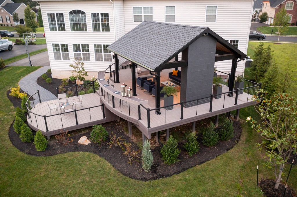
Not every deck design needs the same type of foundation. A ground-level deck may look fine with straight piers, which ease digging and pouring. For an upper deck with a landscaped backyard below, a belled pier may be the way to go, providing for larger bearing areas, but without as much concrete in the flowerbeds. Put a roof over that deck and perhaps a pier/footing foundation is a better choice, because it offers more uplift resistance. The roof loads add to the size of the required bearing area, and the projection of the footing under the fill provides for uplift resistance. As long as you are considering all the science behind foundation design, the IRC offers a fair amount of flexibility. It’s your choice as the designer to determine what’s best for each project.
Illustrations by Chuck Lockhart.